
Thermal control system and method

a control system and thermodynamic technology, applied in the direction of process control, lighting and heating equipment, instruments, etc., can solve the problems of stability and precision, and achieve the effects of improving the efficiency of post condensation, reducing the quality level (vapor mass ratio), and increasing the effective heat transfer coefficient (h)

Active Publication Date: 2009-04-23
BE AEROSPACE INCORPORATED
View PDF19 Cites 17 Cited by
  • Summary
  • Abstract
  • Description
  • Claims
  • Application Information

AI Technical Summary

Benefits of technology

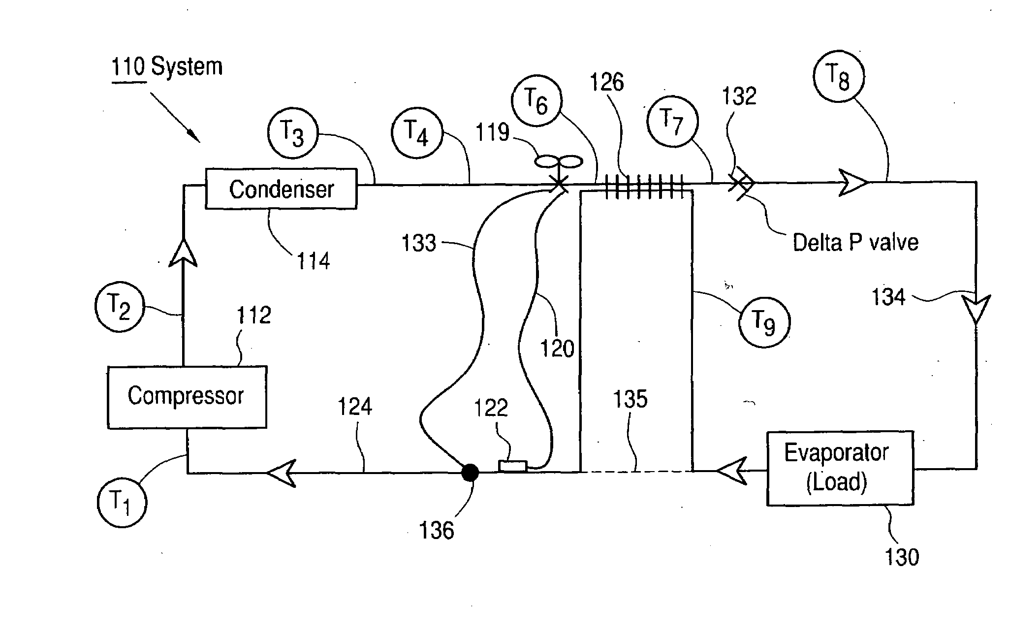
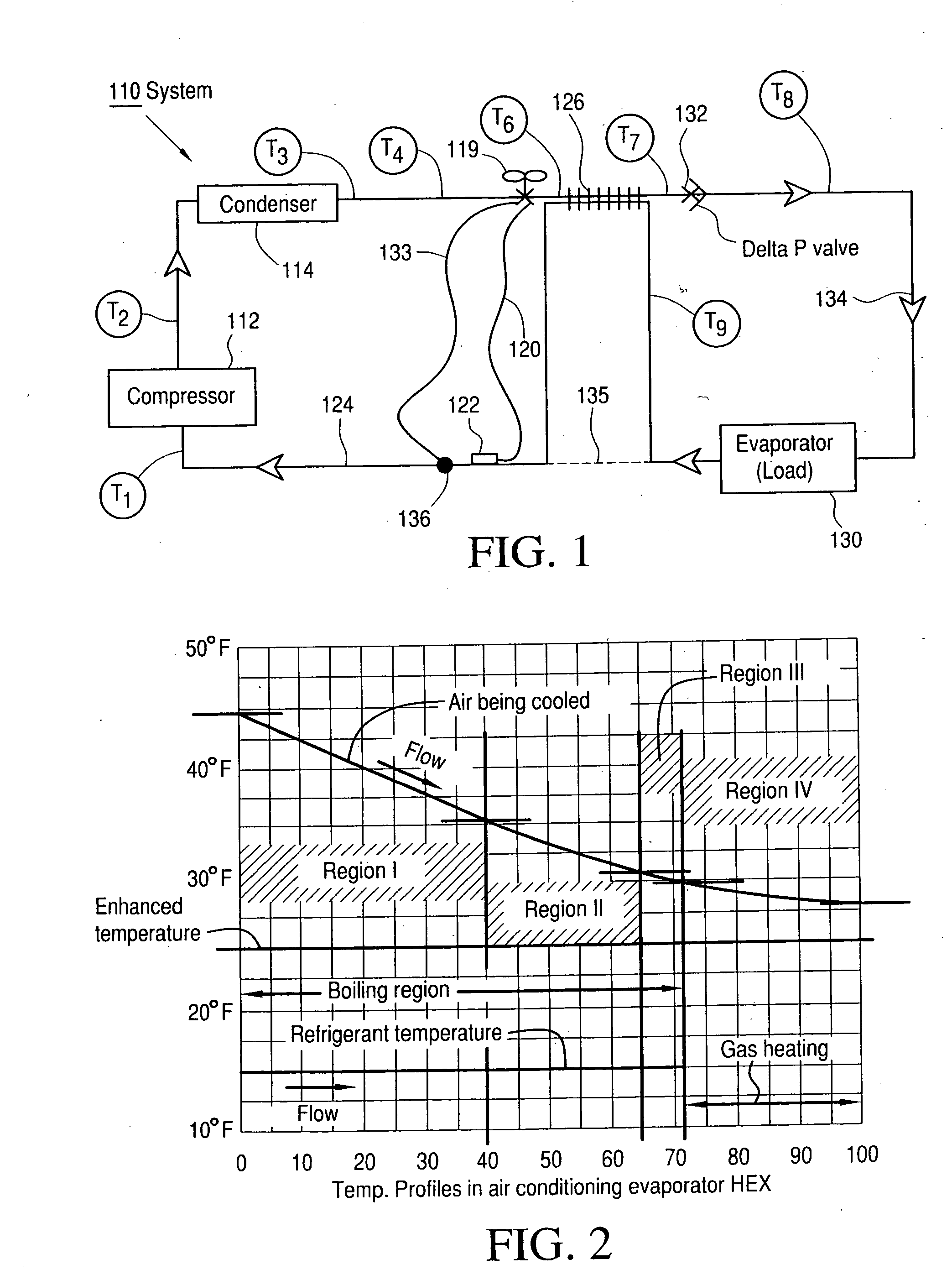
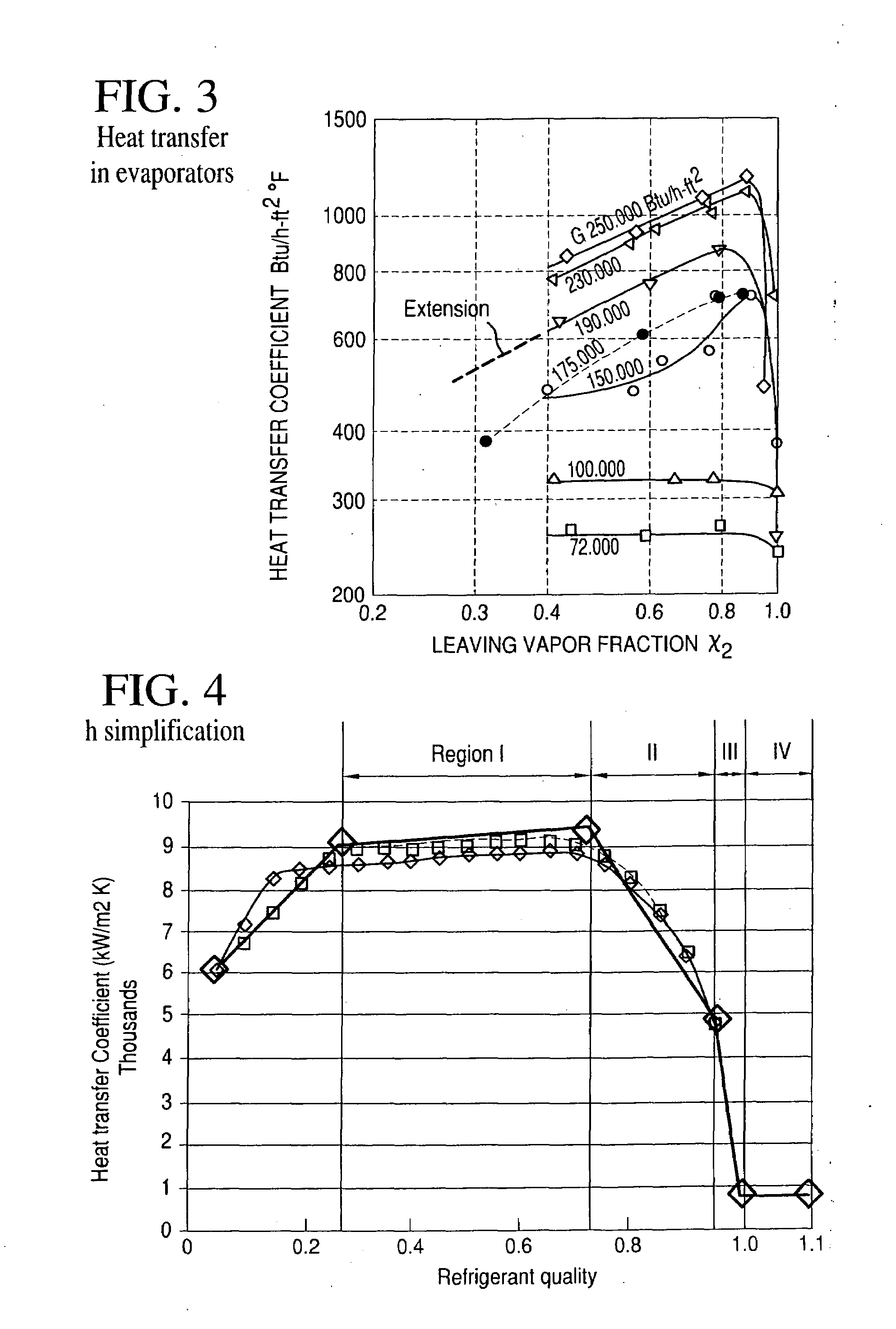
[0010]Improvements in vapor cycle systems used for refrigeration or heat exchange are realized by modifying the conventional vapor cycle to incorporate an additional thermal exchange step after expansion of compressed condensed refrigerant. This interchange of thermal energy is then between the expanded refrigerant and the return flow from the evaporator and is accompanied by a controlled pressure drop, which introduces enhanced post condensing (EPC). The post condensation lowers the quality level (ratio of vapor mass to total mass) of refrigerant delivered to the evaporator and raises the effective heat transfer coefficient (h) during energy exchange with the load. This expedient increases the bulk density of the mass moving through the evaporator and lowers the pressure drop introduced, minimizing heat transfer losses in the low efficiency region of the evaporator. The controlled pressure drop, provided by a pressure dropping device, introduces a substantially constant pressure difference to assure that no expanded vapor and liquid flows during those times when maximum heating is desired.
[0012]Application of this principle to TDSF systems employs the flow of fluids through a supplemental HEX which is generally relatively smaller than the load, and also employs a pressure dropping valve to make a temperature difference available to drive heat across said supplemental HEX so as to introduce further condensation. This combination uniquely effects TDSF system operation by acting to limit and smooth out deviations in temperature changes as well as increasing system efficiency. Small changes in temperature level can be introduced by precise valve regulation of the flow of hot gas into the mixture.

Problems solved by technology

If a slightly higher temperature is needed and / or operation is to be at a low flow or power level, the situation is different, because the pressurized hot gas source presents a much larger potential energy input (than does condensed liquid vapor input after expansion) so that stability and precision can be problematic if temperature is to be raised a relatively small amount.

Method used


Image

  • Thermal control system and method
  • Thermal control system and method
  • Thermal control system and method

Examples


Embodiment Construction

[0026]An exemplary thermal control system which includes the EPC, shown by way of example only, which may advantageously be a commercial air cooling system, is depicted in the block diagram view of FIG. 1, to which reference is now made. In this Figure, for convenience in referring to different points in the thermodynamic cycle, circled numbers (T1) to (T9), are incorporated in the Figure and referred to in this specification. The system 110 comprises a vapor cycle refrigeration system having a conventional compressor 112 which feeds a high pressure, high temperature output as a pressurized gas to a condenser 114. The condenser 114 reduces the refrigerant temperature to a primarily liquid state at ambient or near ambient temperature. The condenser 114 may be liquid or air cooled, and may use a regulated coolant control or be unregulated. The liquefied pressurized product from the condenser 114 is input to an externally equalized thermal expansion valve (hereafter TXV) 119. TXV 119 h...


PUM


Abstract

A system for improving the thermal efficiency of a thermal control loop in which refrigerant after compression and condensation is applied to an evaporator employs a subsidiary counter-current heat exchange intercepting refrigerant flow to maintain the quality of the refrigerant by exchanging thermal energy between the input flow and the output flow from the evaporator. The same principle is effective, with particular advantage when small connections have to be made, in systems using mixed phase media and using the concept of direct energy transfer with saturated fluid.

Description

CROSS-REFERENCE TO RELATED APPLICATIONS[0001]This invention relies for priority on a provisional application filed Oct. 9, 2007 by Kenneth W. Cowans entitled “Improved Vapor Cycle System and Method”, Ser. No. 60 / 998,093 and on a second provisional patent application entitled “Enhanced Post Condensation for System Using Direct Transfer of Saturated Fluids” filed by the same inventor on Jan. 22, 2008, Ser. No. 61 / 011,862.FIELD OF THE INVENTION[0002]This invention relates to thermodynamic systems and methods which utilize vapor cycle processes, such as systems for air conditioning, refrigeration and other temperature control applications, and more particularly to providing improvements in efficiency in such systems and methods by using novel approaches to thermodynamic sequencing.BACKGROUND OF THE INVENTION[0003]Many systems for industrial and residential control of environmental temperatures employ continuous vapor cycle sequences, which have been widely employed and have subsequently...

Claims


Application Information

Patent Timeline
IPC IPC(8): G05D23/00F25B1/00
CPCF25B40/00F25B2400/0403F25B2341/0662F25B2600/2513F25B2600/0261F25B41/39
Inventor COWANS, WILLIAM W.ZUBILLAGA, GLENN W.COWANS, KENNETH W.
Owner BE AEROSPACE INCORPORATED
Learn More