Circuit with improved efficiency and crest factor for current fed bipolar junction transistor (BJT) based electronic ballast

Inactive Publication Date: 2009-04-30
GENERAL ELECTRIC CO
View PDF12 Cites 2 Cited by
  • Summary
  • Abstract
  • Description
  • Claims
  • Application Information

AI Technical Summary

Problems solved by technology

Therefore, a lamp failure in the system can be replaced when it is needed while the remaining lamps are maintained in an “on” state.
A drawback of existing current fed BJT based ballast systems which provide output transformer isolation is that they tend to have an efficiency which is relatively low compared to non-isolated lamp lighting ballasts due to the isolation transformer and operation mode of the BJTs.
Therefore, a particular issue with such BJT based electronic ballasts has to do with the optimization of their base drive to improve the operational efficiency of these devices.
Attempts to optimize the base drive signals commonly results in overdriving of the base-to-emitter junction of the BJT switches.
This is a particular issue where the base of the BJT is driven by a parallel diode-resistor arrangement.
In such configurations, when the base-to-emitter junction is overdriven, an undesirable increase in power dissipation takes place in the BJTs, and a higher circulating current exists in the ballast resulting in lower ballast efficiency.
Another drawback which occurs due to overdriving is that dead-time, i.e., the overlap between the two transistor switching times, increases, leading to a higher current crest factor.
Further, when current fed BJTs are used in conjunction with high efficiency lamp striations are known to occur even at room temperature.

Method used


Image

  • Circuit with improved efficiency and crest factor for current fed bipolar junction transistor (BJT) based electronic ballast
  • Circuit with improved efficiency and crest factor for current fed bipolar junction transistor (BJT) based electronic ballast
  • Circuit with improved efficiency and crest factor for current fed bipolar junction transistor (BJT) based electronic ballast

Examples


Embodiment Construction

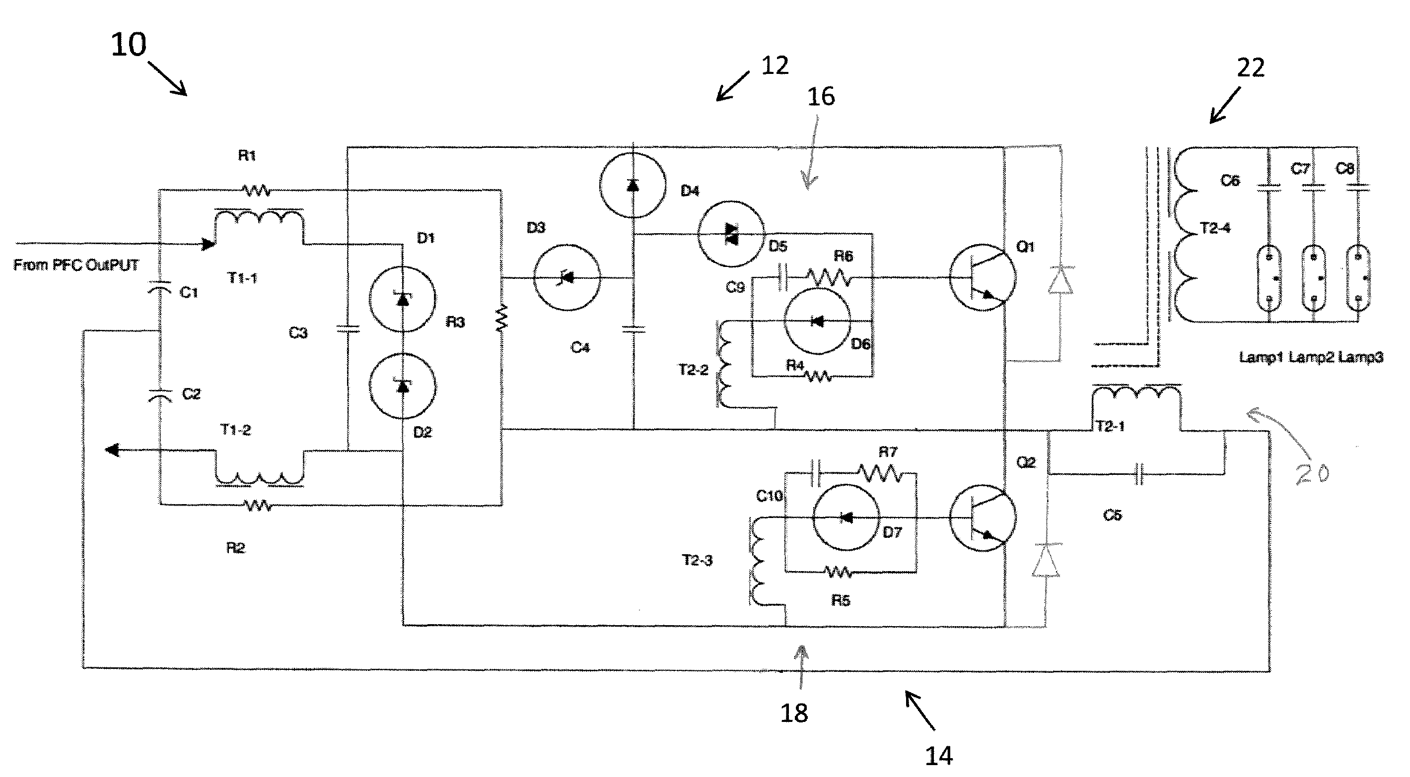
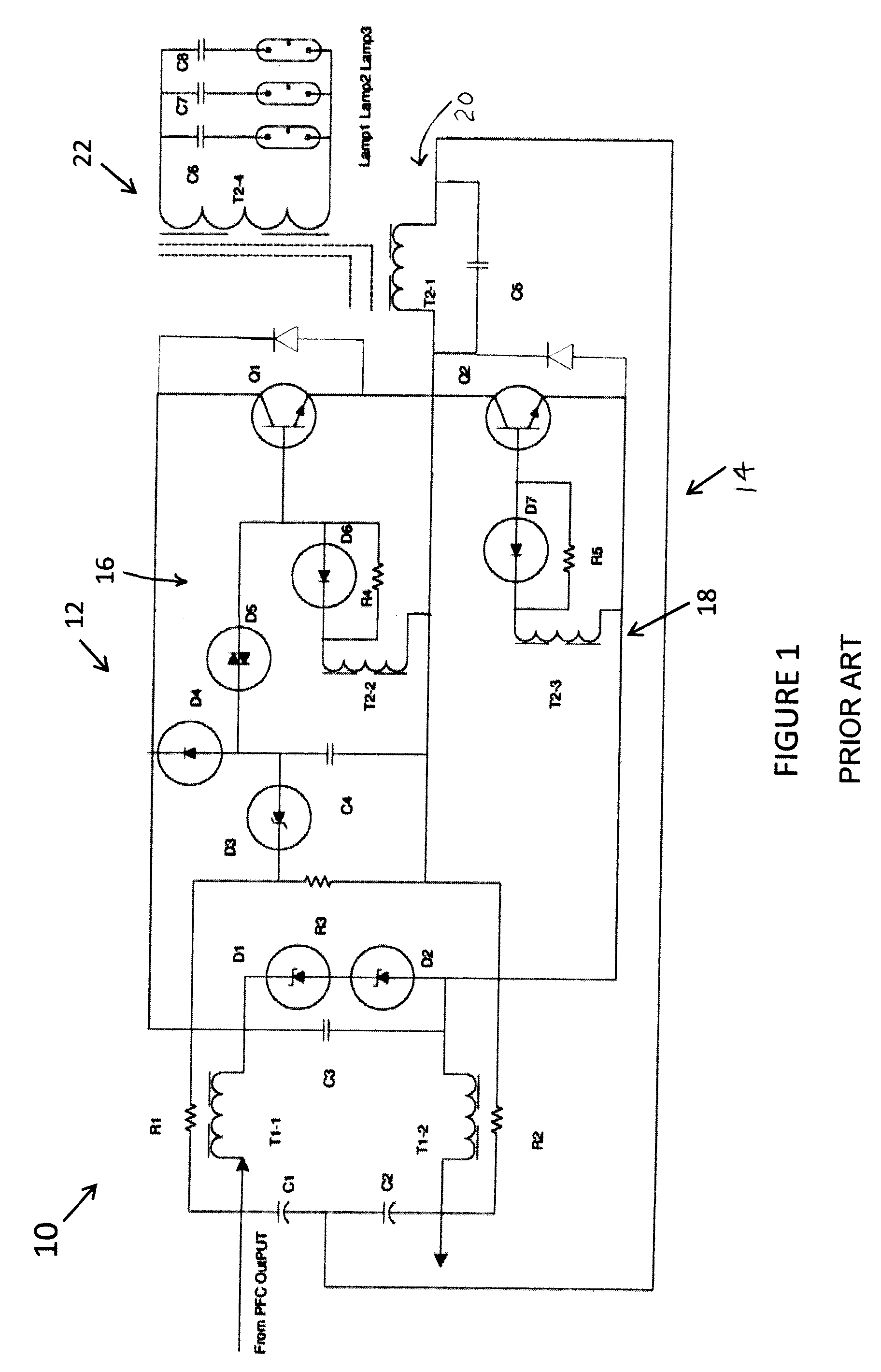
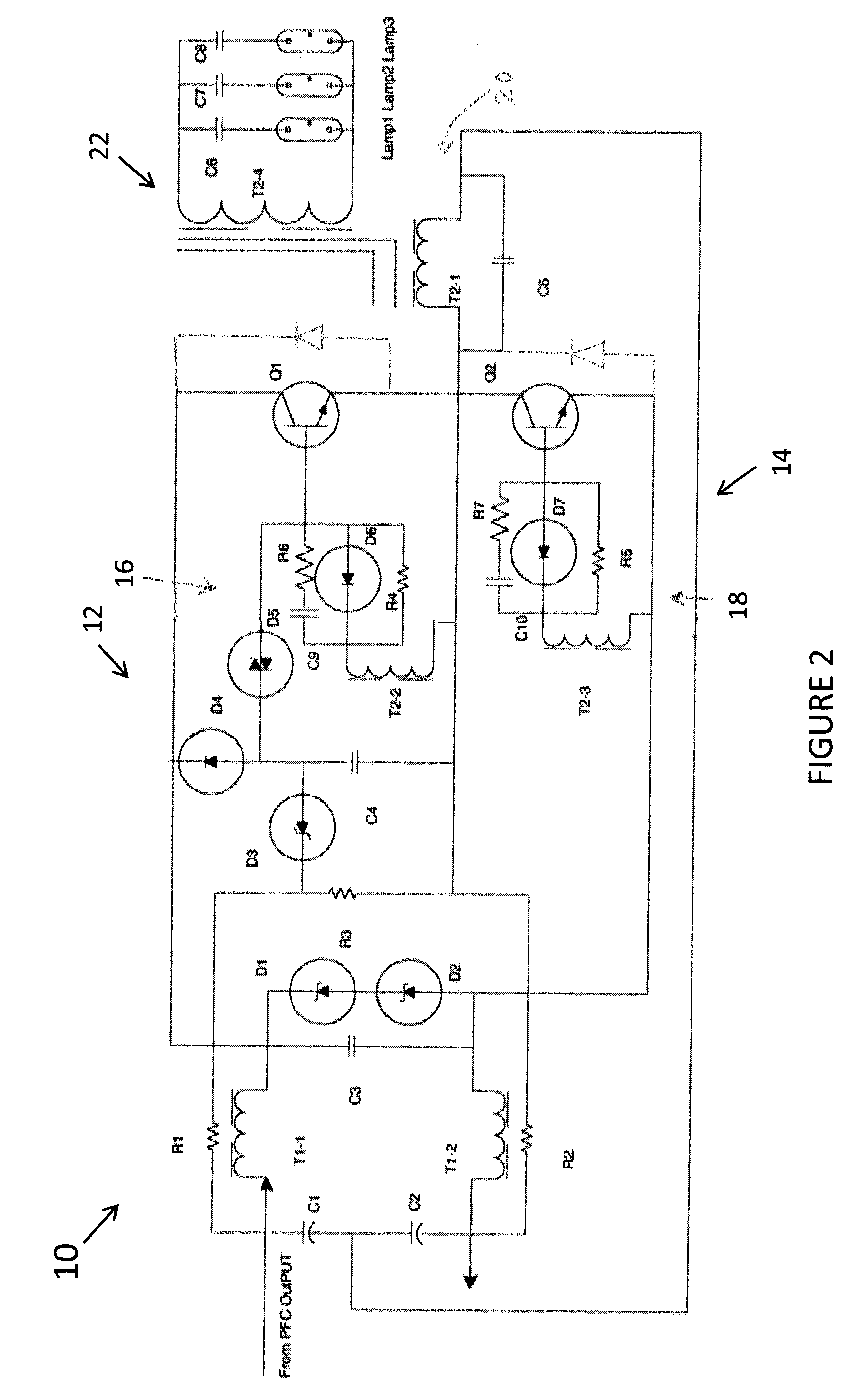
[0011]Turning to FIG. 1, illustrated is a particular circuit in which the concepts of the present application may be employed. It is to be appreciated, however, the concepts described herein are not intended to be limited only to such a circuit, and may be employed in other lamp lighting control circuits. That having been said, FIG. 1 is a half-bridge current fed ballast 10 which includes a first or upper switching configuration 12, and a second or lower switching configuration 14. These switching configurations include BJT switches Q1 and Q2, respectively. BJT switch Q1 is driven by a first or upper BJT control or base drive circuit 16, and BJT switch Q2 is driven by second or lower BJT control or base drive circuit 18. First or upper BJT control circuit includes zener diode D3, capacitor C4, diode D4, diac D5, diode D6, resistor R4, and transformer winding T2-2. Second or lower BJT control circuit 18 is comprised of diode D7, resistor R5 and transformer winding T2-3.

[0012]An outpu...


PUM


Abstract

A current fed bipolar junction transistor (BJT) based inverter ballast includes base drive circuits configured to drive respective BJT switches, and high-speed drive reverse peak current limiting circuits, configured to operate in conjunction with the respective base drive circuits.

Description

BACKGROUND OF THE INVENTION[0001]The present application is directed to lighting devices, and more particularly to ballast circuitry for discharge lamps. Current fed bipolar junction transistor (BJT) based inverter ballasts are widely used in the lamp-lighting industry due to their inherent parallel lamp operation and output transformer isolation features. Providing transformer isolation permits parallel lamp operation and re-lamping of the lighting system to take place without requiring the shutdown of the power inverter of the entire system. Therefore, a lamp failure in the system can be replaced when it is needed while the remaining lamps are maintained in an “on” state. This therefore also reduces the maintenance and operational costs of such systems.[0002]An example of a current fed inverter ballast having an instant program start configuration for use with parallel lamps has been described in U.S. Pat. No. 7,193,368, titled Parallel Lamps With Instant Program start Electronic ...

Claims


Application Information

Patent Timeline
IPC IPC(8): H05B41/16
CPCH05B41/2827H05B41/2825
Inventor CHEN, TIMOTHYKUMAR, NITINSKULLY, JAMES K.
Owner GENERAL ELECTRIC CO
Why Eureka
Try Eureka