
Method for driving an asynchronous motor and pump arrangement with asynchronous motor

a technology of asynchronous motors and pump arrangements, applied in the direction of control systems, pump control, non-positive displacement fluid engines, etc., can solve the problem of greater angular acceleration, and achieve the effect of facilitating the implementation of the method

Inactive Publication Date: 2009-04-30
LINDE AG
View PDF4 Cites 17 Cited by
  • Summary
  • Abstract
  • Description
  • Claims
  • Application Information

AI Technical Summary

Benefits of technology

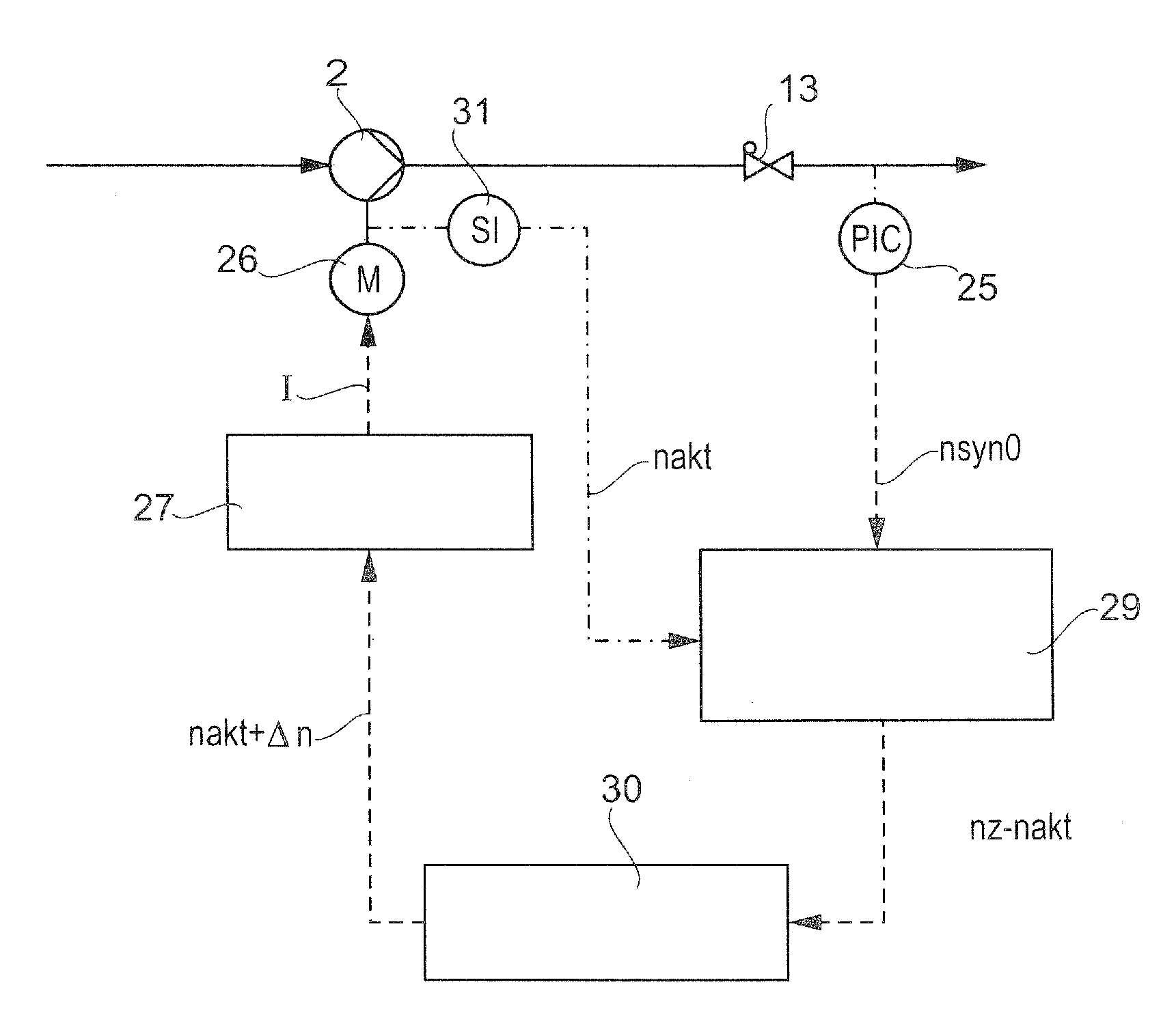
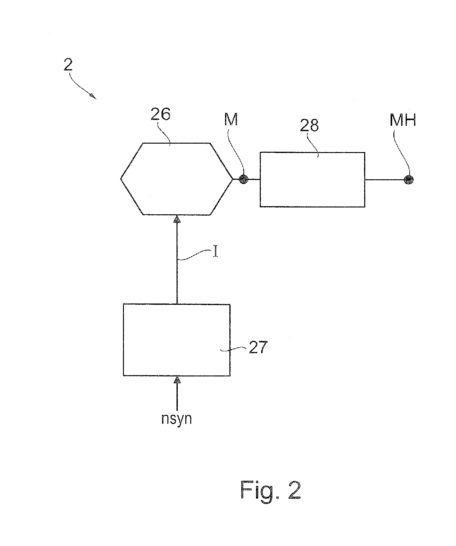
[0014]Updating the three-phase frequency to an updated three-phase frequency which corresponds to the current rotational speed increased by the maximum rotational speed deviation, if the current rotational speed is lower than the target rotational speed and, in particular, is less than the target rotational speed minus the maximum rotational speed deviation. Accordingly, there may be a successive increase in the three-phase frequency such that the asynchronous motor is operated in the proximity of its breakdown point and therefore develops a high torque. By this means a particularly high angular acceleration results during the ramp-up phase, by which means the target rotational speed overall is rapidly achieved.
[0016]In one variant of the method the current rotational speed of the asynchronous motor is determined as a function of a power consumption of the asynchronous motor. Whilst in many closed-loop circuits the power consumption of individual parts of the system can be picked off, for example in the case of an asynchronous motor, the measurement or determination of the rotational speed of a shaft can sometimes be performed only with considerable effort. Generally, however, the current rotational speed can be estimated with the help of a rotational speed-power consumption curve of the asynchronous motor. Consequently, no direct measurement of the rotational speed is necessary, which thus facilitates the implementation of the method.

Problems solved by technology

In the proposed method, the fact is exploited that the motor torque is greatest in the proximity to the breakdown point and thus greater angular acceleration results during ramp-up.

Method used


Image

  • Method for driving an asynchronous motor and pump arrangement with asynchronous motor
  • Method for driving an asynchronous motor and pump arrangement with asynchronous motor
  • Method for driving an asynchronous motor and pump arrangement with asynchronous motor

Examples


Embodiment Construction

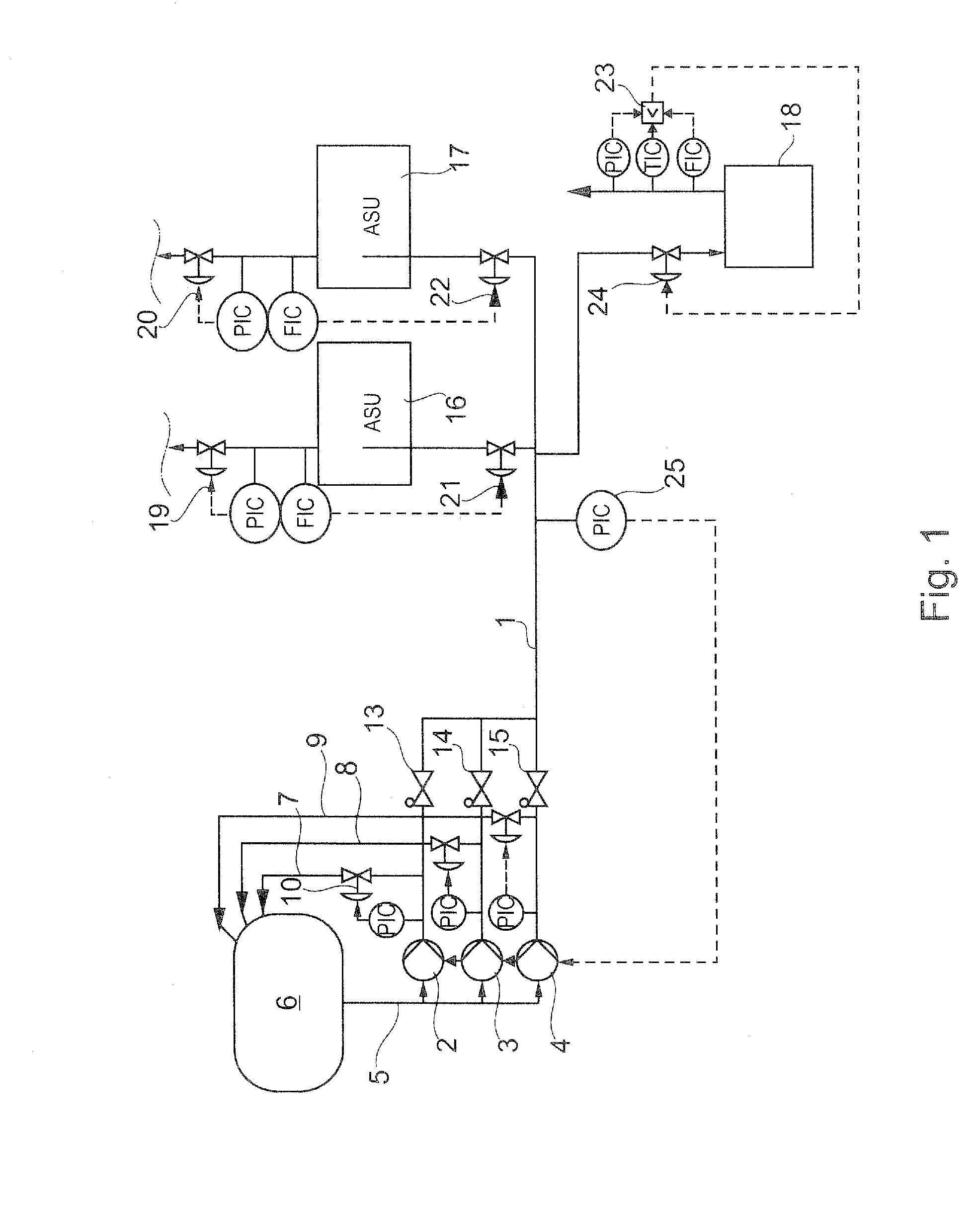
[0030]In the case of air separation units with internal compression, cryogenic air or fluids (LIN, LOX, LAR=liquid nitrogen, oxygen, argon), for example, are brought to an operating pressure by means of pumping or compression and are delivered to a heat exchanger of the corresponding air separation unit (ASU). The corresponding cryogenic fluid is then evaporated therein. In order to allow the particular process to be continued despite the failure of one of the pumps, redundant pumps are provided which on failure of the actual working pump start operating as a substitute pump. It is also conceivable that several individual system parts are provided with pressurized cryogenic fluid from a common reservoir or tank. This is schematically shown in FIG. 1, for example.

[0031]A common high-pressure fluid line 1 is provided which is supplied with high-pressure fluid by three pumps 2, 3, 4. The pumps draw the particular product via a feed line 5 from a common reservoir or tank 6. For each pum...


PUM


Abstract

A method for driving an asynchronous motor operated at an adjustable three-phase frequency to a predetermined target rotational speed is disclosed. For controlling the asynchronous motor in an operating range around its breakdown point a current rotational speed of the asynchronous motor is determined at predetermined intervals and the three-phase frequency is adjusted stepwise such that the current rotational speed lies within a predetermined maximum rotational speed deviation of an updated three-phase frequency.

Description

BACKGROUND OF THE INVENTION[0001]The present invention relates to a method of driving an asynchronous motor as is used in pumps, for example. The invention further relates to an arrangement with one or more pumps for providing pressurized cryogenic fluid, this arrangement being suitable for use in an air liquefaction unit, for example.[0002]The driving and control of electric motors, and asynchronous motors in particular, which are driven with three-phase alternating current is necessary in various fields of use. Corresponding electric motors may be used, for example, for driving pumps. Frequently cryogenic pumps are used, in other words pumps which deliver cryogenic fluids at temperatures of less than −170° C. with corresponding three-phase asynchronous motors. Particularly in the case of low-temperature applications, such as for example air separation units, a cryogenic fluid such as liquefied air is brought by cryogenic pumps to a predetermined operating pressure and is then pass...

Claims


Application Information

Patent Timeline
IPC IPC(8): H02P27/04
CPCH02P27/045F04D15/0066
Inventor HAAS, SEBASTIAN
Owner LINDE AG
Learn More