Display panel control device, liquid crystal display device, electronic appliance, display device driving method, and control program

a technology of liquid crystal display device and control device, which is applied in the direction of electric digital data processing, instruments, computing, etc., can solve the problems of not being able to reach the prescribed luminance, the liquid crystal response is delayed, and the image quality is affected, so as to prevent the effect of generation

Active Publication Date: 2009-04-30
NEC LCD TECH CORP
View PDF8 Cites 62 Cited by
  • Summary
  • Abstract
  • Description
  • Claims
  • Application Information

AI Technical Summary

Benefits of technology

[0017]The present invention has been designed to overcome the points of the above-described technique which need to be improved. An exemplary object of the invention is to provide a display panel control device, a liquid crystal display device, an el

Problems solved by technology

However, even when normal overshoot (emphasis adjustment) is applied on the video signal in the black insertion drive with the liquid crystal display device of Patent Document 1, there is delay caused in response of the liquid crystal if there is a difference generated in the gradation voltage values (gradation voltages) of the video signals between a given frame and another frame.
Because of this, it is not possible to reach a prescribed luminance within a video display period of another frame.
As a result, as shown in FIG. 47, there are points that need to be improved in the video display, such as generation of step-like tailing, etc., and ghost generated in scroll-display of letters, which causes bad influences on the image quality.
Thus, when the gradation value of the video si

Method used


Image

  • Display panel control device, liquid crystal display device, electronic appliance, display device driving method, and control program
  • Display panel control device, liquid crystal display device, electronic appliance, display device driving method, and control program
  • Display panel control device, liquid crystal display device, electronic appliance, display device driving method, and control program

Examples


first exemplary embodiment

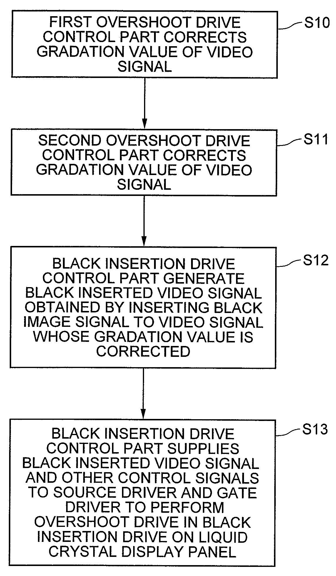
[0085]First, specific structures of the liquid crystal display device according to this exemplary embodiment will be described starting from the overall structure. Then, detailed structure of a controller, functions of a black insertion drive control part, and entire schematic operations as will be described.

(Overall Structure of Liquid Crystal Display Device)

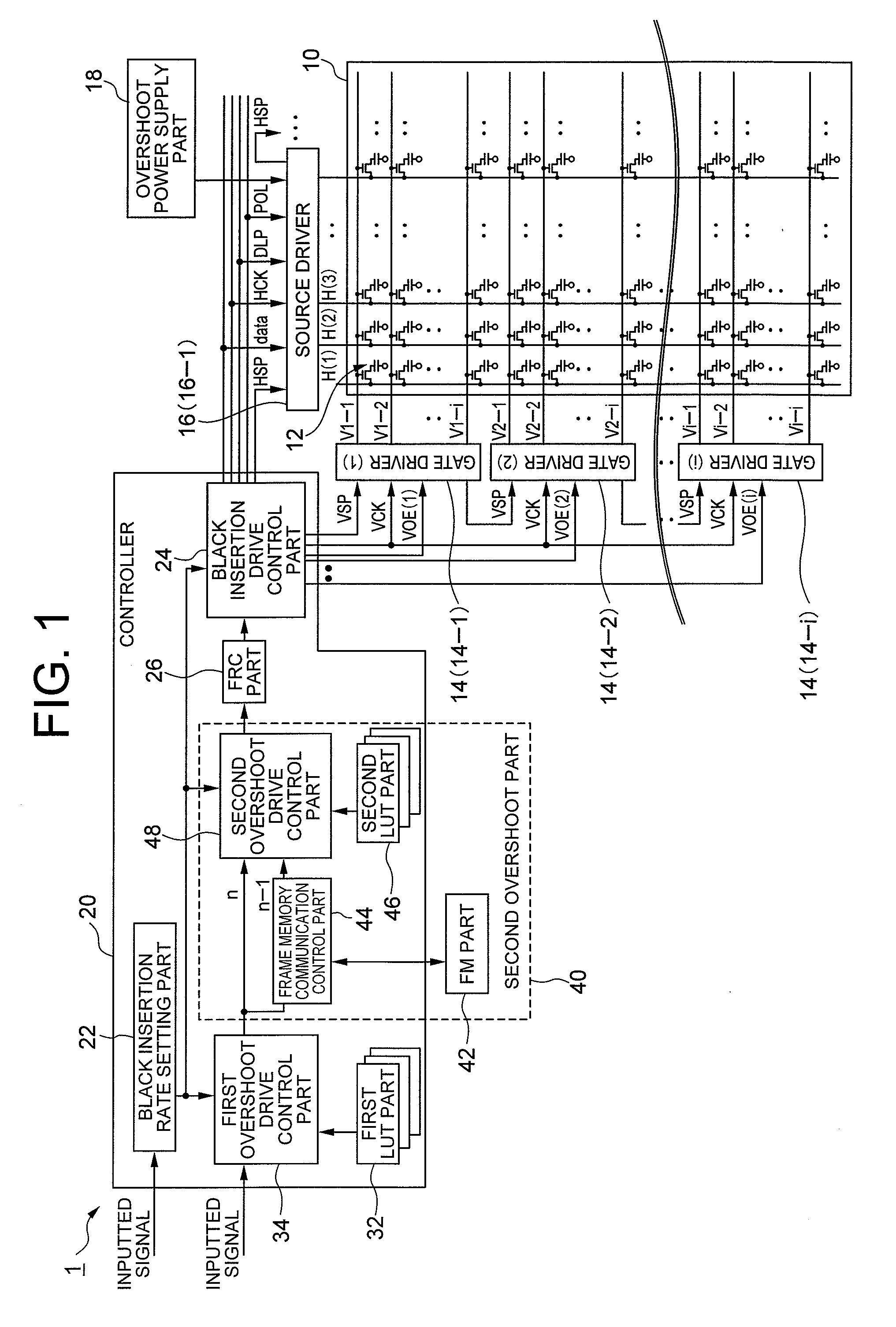
[0086]The overall structure of the liquid crystal display device according to this exemplary embodiment of the invention will be described by referring to FIG. 1. FIG. 1 is a block diagram showing an example of the overall structure of the liquid crystal display device according to the first exemplary embodiment of the invention.

[0087]The liquid crystal display device 1 of the exemplary embodiment is capable of performing the first and second overshoot drives in the black insertion drive. As shown in FIG. 1, the liquid crystal display device 1 is structured to include a liquid crystal display panel 10, gate drivers 14 (14-1 to ...

second exemplary embodiment

[0246]Next, a second exemplary embodiment of the invention will be described by referring to FIG. 25-FIG. 32. Hereinafter, explanations regarding structures and the processing orders which are substantially the same as those of the first exemplary embodiment are omitted, and only the different points are described. FIG. 25 is a block diagram showing an example of the second exemplary embodiment in which the display panel control device according to the present invention is applied to a liquid crystal display device. In FIG. 25, same reference numerals are applied to the structures that are same as those of the first exemplary embodiment shown in FIG. 1.

[0247]With the first exemplary embodiment above, the accumulative luminance reaching delay is corrected by correcting the gradation value of the video display by executing the second overshoot drive. However, the second exemplary embodiment is structured to correct the accumulative luminance reaching delay by correcting the gradation ...

third exemplary embodiment

[0291]Next, a third exemplary embodiment of the present invention will be described by referring to FIG. 33. Hereinafter, explanations regarding structures and the processing orders which are substantially the same as those of the first exemplary embodiment are omitted, and only the different points are described. FIG. 33 is a block diagram showing an example of the third exemplary embodiment in which a liquid crystal display device having the display panel control device of the present invention is applied to a broadcast receiver.

[0292]As shown in FIG. 33, a broadcast receiver 200 is configured to include a liquid crystal display device 274 having the same structure as those described in any of the above-described exemplary embodiments.

[0293]Further, the broadcast receiver 200 is configured to include: an analog tuner 202 for terrestrial analog broadcasting; a demodulator 204 for demodulating signals from the analog tuner 202; a terrestrial digital tuner 212 for terrestrial digital...


PUM


Abstract

To provide a display panel control device capable of preventing generation of step-like tailing and ghost when executing black insertion drive. A first correction device performs first correction on a gradation value of a video signal by considering response delay of the display panel when changing from a second gradation voltage to a first gradation voltage. A second correction device performs second correction on one of or both of the gradation value of the video signal and the gradation voltage of a monochrome image signal by considering accumulative luminance reaching delay of the video part caused due to a difference between each monochrome display luminance of each monochrome image part in different unit frame cycle periods, when the gradation value of the video signal changes from a unit frame cycle period to another unit frame cycle period. A monochrome image insertion drive control device generates the monochrome image inserted video signal including the video part and the monochrome image part to which the first correction or the second correction is performed, and controls the monochrome image insertion drive of the display panel.

Description

CROSS-REFERENCE TO RELATED APPLICATION[0001]This application is based upon and claims the benefit of priority from Japanese patent application No. 2007-276078, filed on Oct. 24, 2007, the disclosure of which is incorporated herein in its entirety by reference.BACKGROUND OF THE INVENTION[0002]1. Field of the Invention[0003]The present invention relates to a display panel control device, a liquid crystal display device, an electric appliance, a display device driving method, and a control program.[0004]2. Description of the Related Art[0005]A hold-type display device holds an image as a still image within a frame period, and displays a dynamic image by switching a screen for every frame. With dynamic image displays provided on the hold-type display device, still images are switched and displayed continuously without a break from frame to frame. Thus, human beings whose eyesight moves by following the dynamic image display perceive still images held still as images that are superimpose...

Claims


Application Information

Patent Timeline
IPC IPC(8): G09G5/10G02F1/133G09G3/20G09G3/36
CPCG09G3/3666G09G3/3688G09G2310/04G09G2360/18G09G2320/02G09G2320/0238G09G2320/0285G09G2310/061
Inventor KIMURA, HIROAKI
Owner NEC LCD TECH CORP
Why Eureka
Try Eureka