Display apparatus

a technology of display apparatus and pixel electrode, applied in non-linear optics, instruments, optics, etc., can solve problems such as differences in pixel electric potential applied to pixel electrodes, and achieve the effect of maintaining display quality

Active Publication Date: 2009-04-30
JAPAN DISPLAY WEST
View PDF3 Cites 34 Cited by
  • Summary
  • Abstract
  • Description
  • Claims
  • Application Information

AI Technical Summary

Benefits of technology

[0029]As described above, in accordance with the present invention, a liquid-crystal display apparatus for showing color displays is capable of controlling the color tone of a display while controlling uniformly of pixels each provided for one of different colors.

Problems solved by technology

As a result, there are differences among pixel electric potentials applied t

Method used


Image

  • Display apparatus
  • Display apparatus
  • Display apparatus

Examples


first embodiment

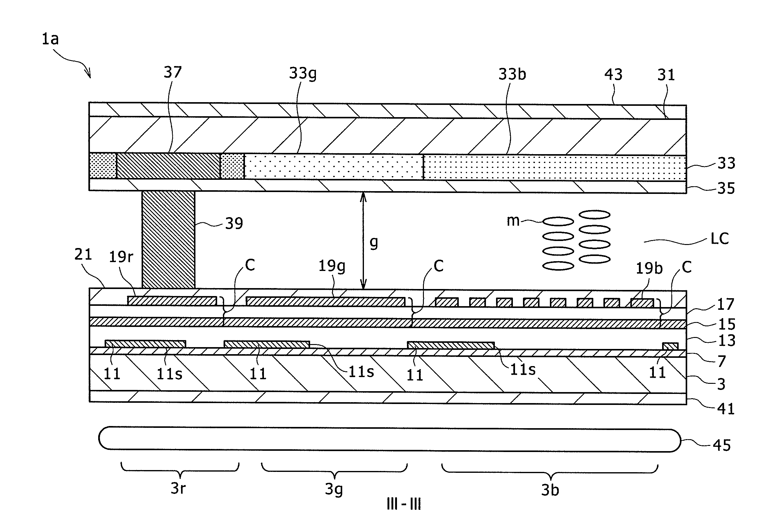
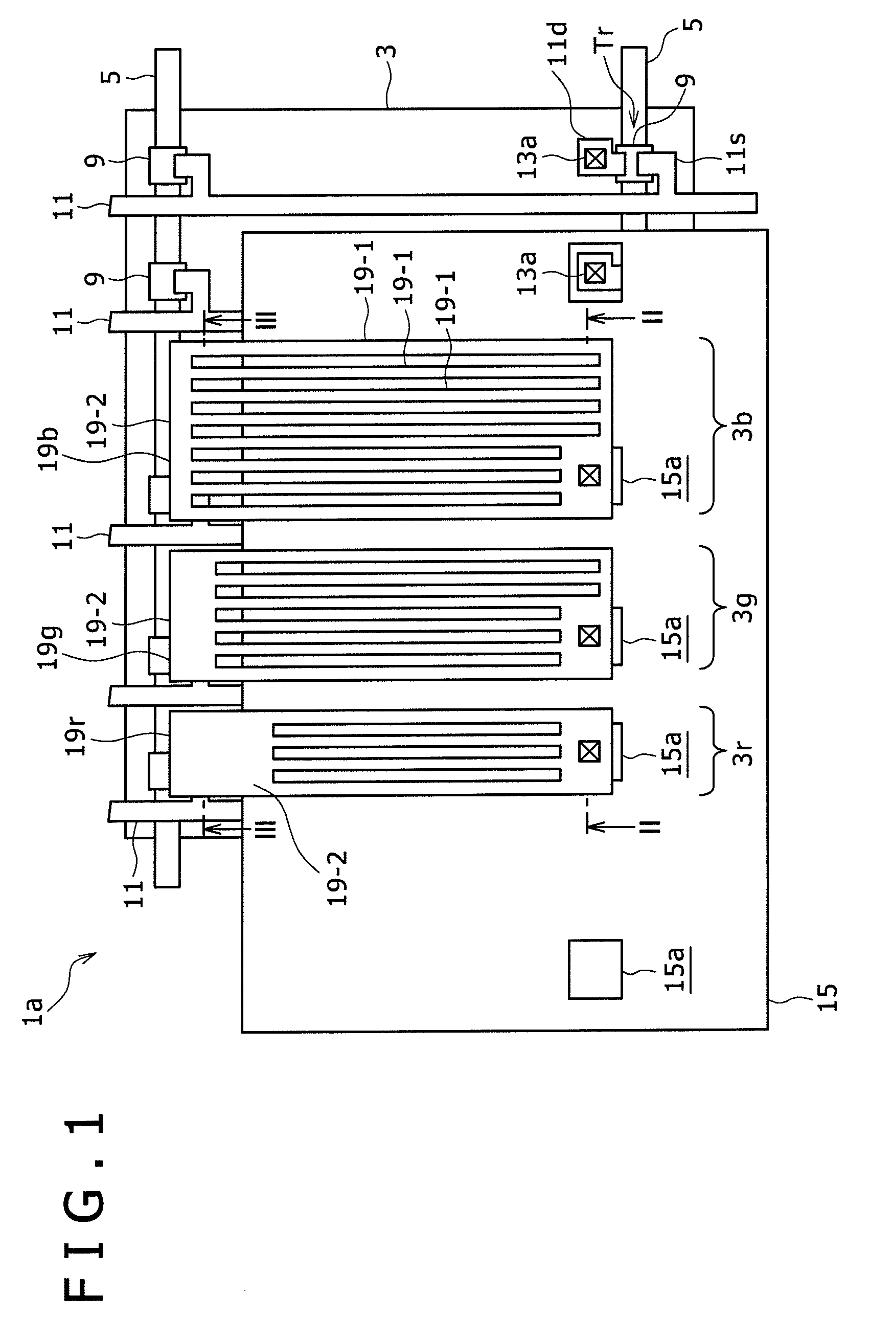
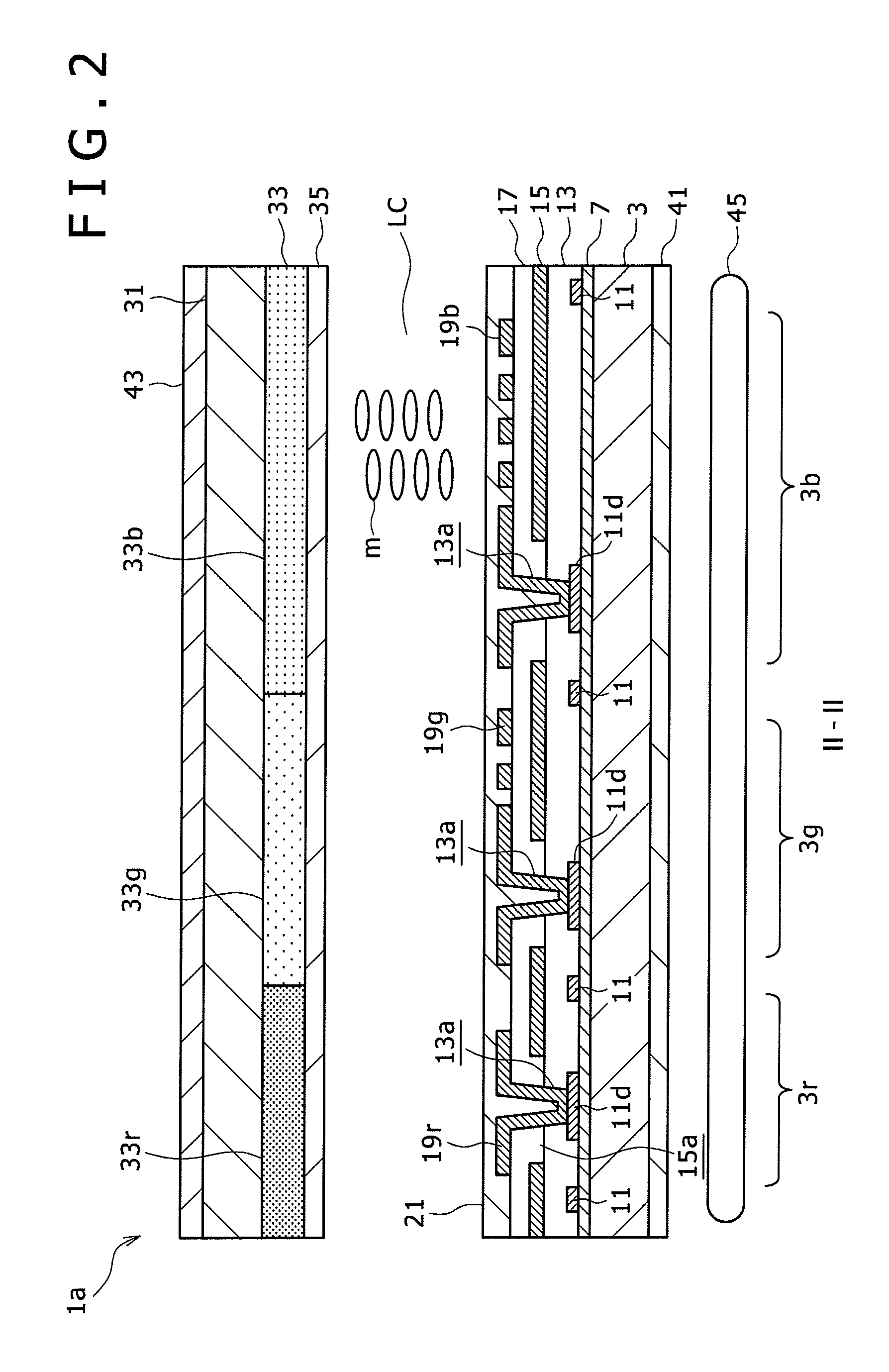
[0046]FIG. 1 is an explanatory diagram referred to in description of the configuration of a liquid-crystal display apparatus la according to a first embodiment of the present invention as a diagram showing a top view of a driving-substrate model of the liquid-crystal display apparatus. FIG. 2 is a cross-sectional diagram showing a II-II cross section shown in the top-view diagram of FIG. 1. FIG. 3 is a cross-sectional diagram showing a III-III cross section shown in the top-view diagram of FIG. 1. Each of FIGS. 1 to 3 is a diagram showing three pixels, i.e., a red-color pixel 3r, a green-color pixel 3g and a blue-color pixel 3b which form a set of color pixels in the liquid-crystal display apparatus 1a according to the first embodiment of the present invention. It is to be noted that the top-view diagram of FIG. 1 does not show some configuration elements such as insulation and orientation films.

[0047]The liquid-crystal display apparatus 1a shown in the top-view diagram of FIG. 1, t...

second embodiment

[0084]FIG. 4 is an explanatory diagram referred to in description of the configuration of a liquid-crystal display apparatus 1b according to a second embodiment of the present invention as a diagram showing a top view of a driving-substrate model of the liquid-crystal display apparatus. FIG. 5 is a cross-sectional diagram showing a V-V cross section shown in the top-view diagram of FIG. 4. FIG. 6 is a cross-sectional diagram showing a VI-VI cross section shown in the top-view diagram of FIG. 4. Each of FIGS. 4 to 6 is a diagram showing three pixels, i.e., a red-color pixel 3r, a green-color pixel 3g and a blue-color pixel 3b which form a set of color pixels in the liquid-crystal display apparatus 1b according to the second embodiment of the present invention. It is to be noted that the top-view diagram of FIG. 4 does not show some configuration elements such as insulation and orientation films.

[0085]The liquid-crystal display apparatus 1b shown in the top-view diagram of FIG. 4 as w...

application examples

[0097]The liquid-crystal display apparatus according to the embodiment of the present invention described above is typically employed in a variety of electronic instruments shown in diagrams of FIGS. 7 to 11 as instruments used in all fields. Examples of the electronic instruments are a digital camera, a notebook personal computer, a portable terminal such as a cellular phone and a video camera. In each of these electronic instruments, the liquid-crystal display apparatus is used for displaying a video signal supplied thereto or generated therein as an image or a video. The following description explains concrete implementations of the electronic instrument to which the present invention is applied.

[0098]FIG. 7 is a diagram showing a squint view of the external appearance of a TV set to which an embodiment of the present invention is applied. The TV set serving as a typical implementation of the electronic instrument to which the present invention is applied employs a front panel 10...


PUM


Abstract

Disclosed herein is a display apparatus including a first substrate patterned to create pixel electrodes, a second substrate placed to face the first substrate and a liquid-crystal layer sandwiched by the first and second substrates wherein: one of the first and second substrates is patterned to create color filters each provided for one of a plurality of different colors as color filters each associated with one of the pixel electrodes each included in one of pixels each provided for one of the different colors; each of the pixels each provided for one of the different colors has a pixel area which varies from color to color; and the ratio of the electrode area of any particular one of the pixel electrodes to the pixel area of the pixel that includes the particular pixel electrode varies from color to color.

Description

CROSS REFERENCES TO RELATED APPLICATIONS[0001]The present invention contains subject matter related to Japanese Patent Application JP 2007-283160 filed in the Japan Patent Office on Oct. 31, 2007, the entire contents of which being incorporated herein by reference.BACKGROUND OF THE INVENTION[0002]1. Field of the Invention[0003]In general, the present invention relates to a display apparatus. In particular, the present invention relates a display apparatus for driving liquid-crystal molecules in an FFS (Fringe Field Switching) mode.[0004]2. Description of the Related Art[0005]In the field of liquid-crystal display apparatus operating in a horizontal electric-field mode, attention is paid to a liquid-crystal mode for implementing a large visual field angle and high contrast. In particular, in comparison with an IPS (In-Plane Switching) mode, the FFS (Fringe Field Switching) mode provides an improved aperture ratio and an improved transmission.[0006]FIG. 12 is a plurality of diagrams e...

Claims


Application Information

Patent Timeline
IPC IPC(8): G02F1/136G02F1/1335
CPCG02F1/134363G02F2201/52G02F2001/134372G02F1/136213G02F1/134372G02F1/1335G02F1/1343
Inventor TANAKA, HIRONAOYAMAGUCHI, HIDEMASASAKURAI, YOSHIHIRO
Owner JAPAN DISPLAY WEST
Why Eureka
Try Eureka