

Back-light assembly
a backlight and assembly technology, applied in the field of backlight systems, can solve the problems of inability to illuminate a large display, heat generated by light sources, and limit the size of edge-lit back-lights, and achieve the effect of uniform illumination of large display areas and high efficiency
- Summary
- Abstract
- Description
- Claims
- Application Information
AI Technical Summary
Benefits of technology
Problems solved by technology
Method used
Image

Examples
first embodiment
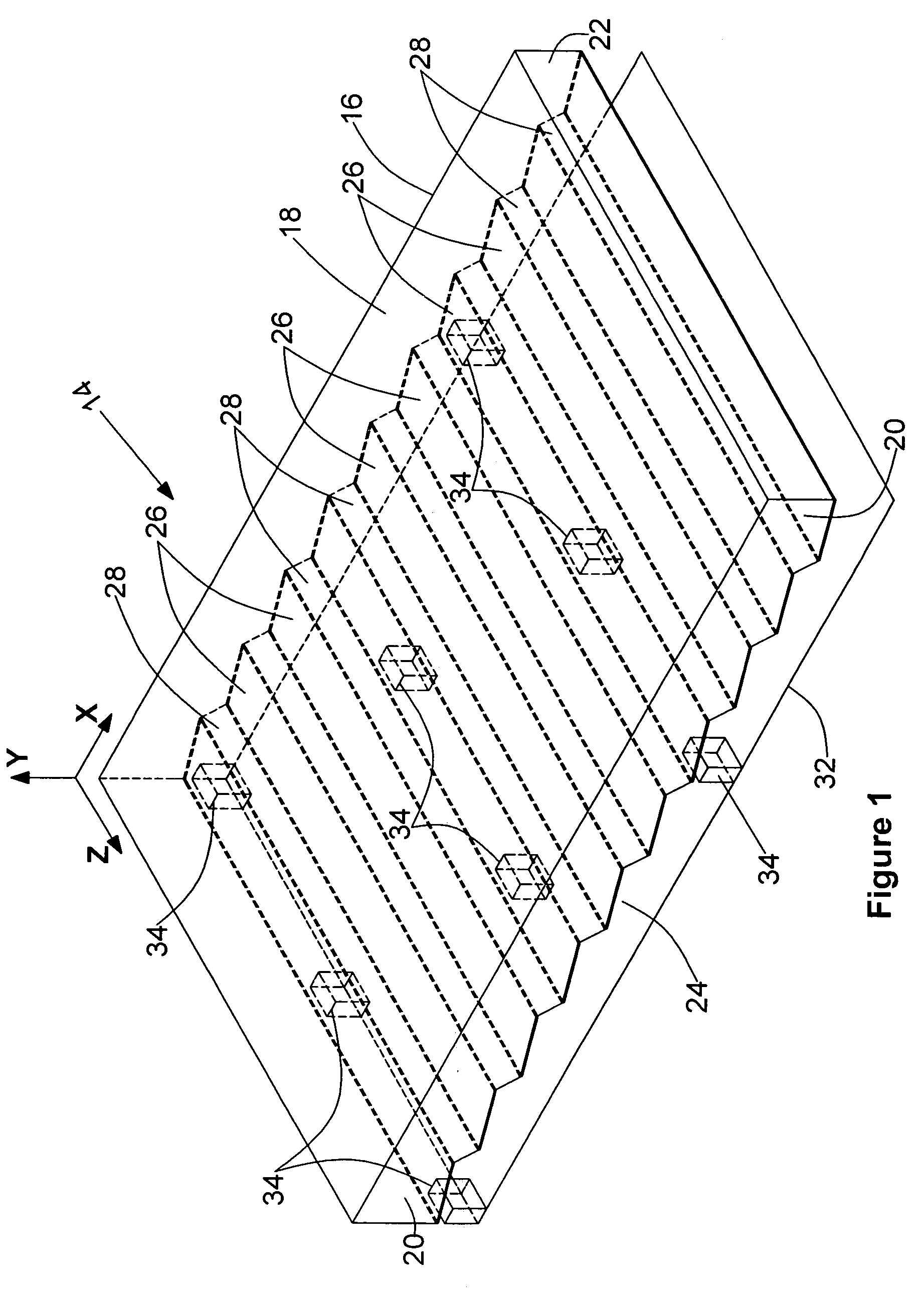
[0023]Disposed between reflector panel 32 and lower surface 24 of the waveguide is a plurality of transversely spaced-apart light sources 34. In this first embodiment of the invention, light sources 34 comprise side-mounted light emitting diodes having 120 degree emission angles that emit light in the direction of X-axis (see FIG. 2). It is to be understood that light sources 34 can be of various types including cold cathode fluorescent lamps with side-mounted reflectors the character of which presently is described.
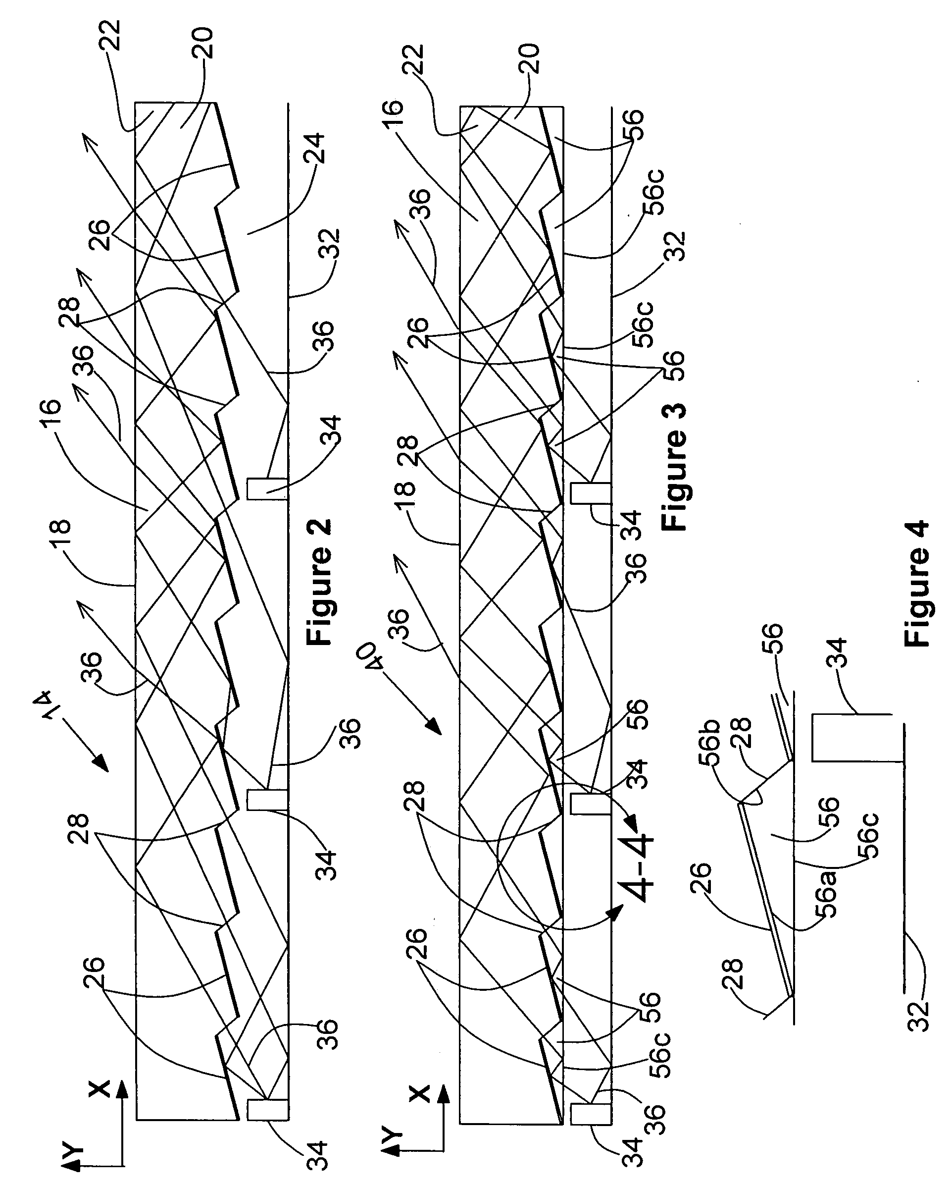
[0024]Referring to FIG. 2 of the drawings, it is to be noted that certain of the light rays 36 that are generated by the light sources 34 enter into the waveguide 16 directly from the light coupling facets 28. Additionally, depending on the angles that light rays 36 reflect from light-reflecting facets 26 and the upper surface of reflector panel 32, and also enter the waveguide 16 from the light coupling facets 28. Inside the waveguide 16 light rays 36 propagate in the X...
second embodiment
[0026]Turning next to FIGS. 3 and 4, an alternate form of the back-light assembly of the invention is there illustrated and generally designated by the numeral 40. This latest embodiment is similar in some respects to the embodiment shown in FIGS. 1 and 2 of the drawings and like numbers are used in FIGS. 3 and 4 to identify like components. As indicated in FIG. 3, back-light assembly 40 here comprises an optical waveguide 16. An important feature of this second embodiment of the back-light assembly of the invention resides in the provision of a plurality of spaced-apart micro-prisms 56 that are disposed proximate lower surface 24 of the waveguide 16. As indicated in FIGS. 3 and 4 of the drawings, each micro-prism 56 has a first facet 56a optically coupled to a selected one of the light-reflecting facets 26. In a similar fashion, a second facet 56b is optically coupled to a selected one of the downwardly inclined facets 28. Each micro-prism 56 also includes a light coupling third fa...
third embodiment
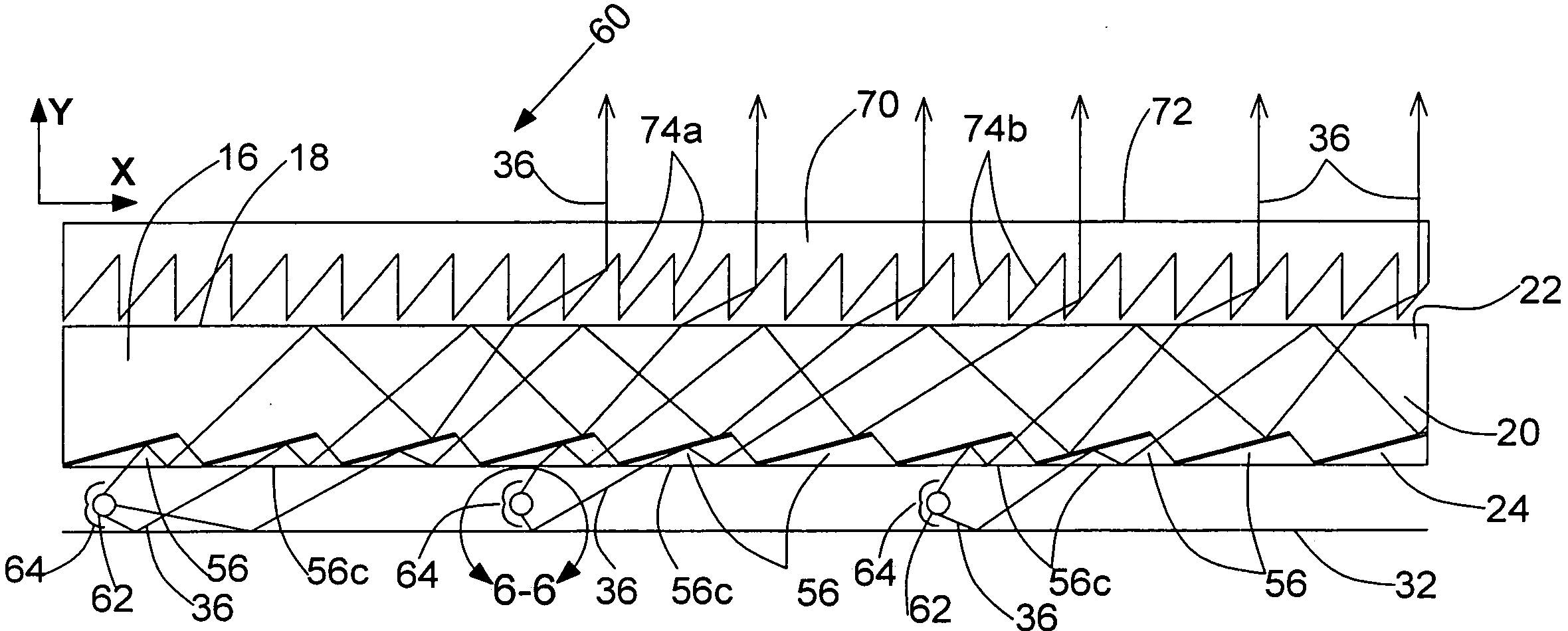
[0034]Referring now to FIG. 5, still another form of the back-light assembly of the invention is there illustrated and generally designated by the 60. This latest embodiment is similar in many respects to the embodiment shown in FIGS. 3 and 4 of the drawings and like numbers are used in FIG. 5 to identify like components. The main differences between this third embodiment of the invention and that shown in FIGS. 3 and 4 reside in the provision of a different type of light source and in the addition of a prism film 70 that is positioned adjacent the upper surface of the waveguide 16.
[0035]As before, the back-light assembly 60 here comprises an optical waveguide 16 that includes an upper, generally flat surface 18, a first side surface 20, a second side surface 22 and a specially configured lower surface 24 that is identical to the lower surface described in connection with the embodiment of FIGS. 3 and 4.
[0036]Like the embodiment in FIGS. 3 and 4, this third embodiment of the inventi...
PUM
 Abstract
Description
Claims
Application Information