
Layer-2 Redundancy Protocol Interconnection Device

a protocol interconnection and protocol technology, applied in the field of layer2 redundancy protocol interconnection devices, can solve the problems of inability to recover communications, delay in communication recovery, and take a long time to establish communication recovery, so as to prevent a large loop of the whole network and loss of communication arrivability, prevent delay of communication route switching, and high-speed communication route switching

Inactive Publication Date: 2009-04-30
ALAXALA NETWORKS
View PDF3 Cites 49 Cited by
  • Summary
  • Abstract
  • Description
  • Claims
  • Application Information

AI Technical Summary

Benefits of technology

[0022]The present invention therefore settles the above-described issues, provides interconnection for a plurality of redundancy protocols in networks, prevents a large loop in the whole network, preserves communication arrivability in each architecture network segment under control of each redundancy protocol, enables update of MAC address learning results, and realizes high speed switching of a communication route without network architecture restrictions regarding provision of interconnection and without dependency upon time-out of a control packet, to thereby realize flexible network design adopting a redundancy protocol suitable for each architecture network segment. Further, when a network is configured by using one redundancy protocol, protocol processes associated with switching of a communication route are localized to reduce a load associated with a failure and an architecture change and facilitate the architecture change.

Problems solved by technology

For example, since there are a number of edge networks, the reconfiguration of all networks is difficult so that reuse of already existing networks is desired, whereas the core network is desired to reduce the wiring amount of communication routes because of a distance issue.
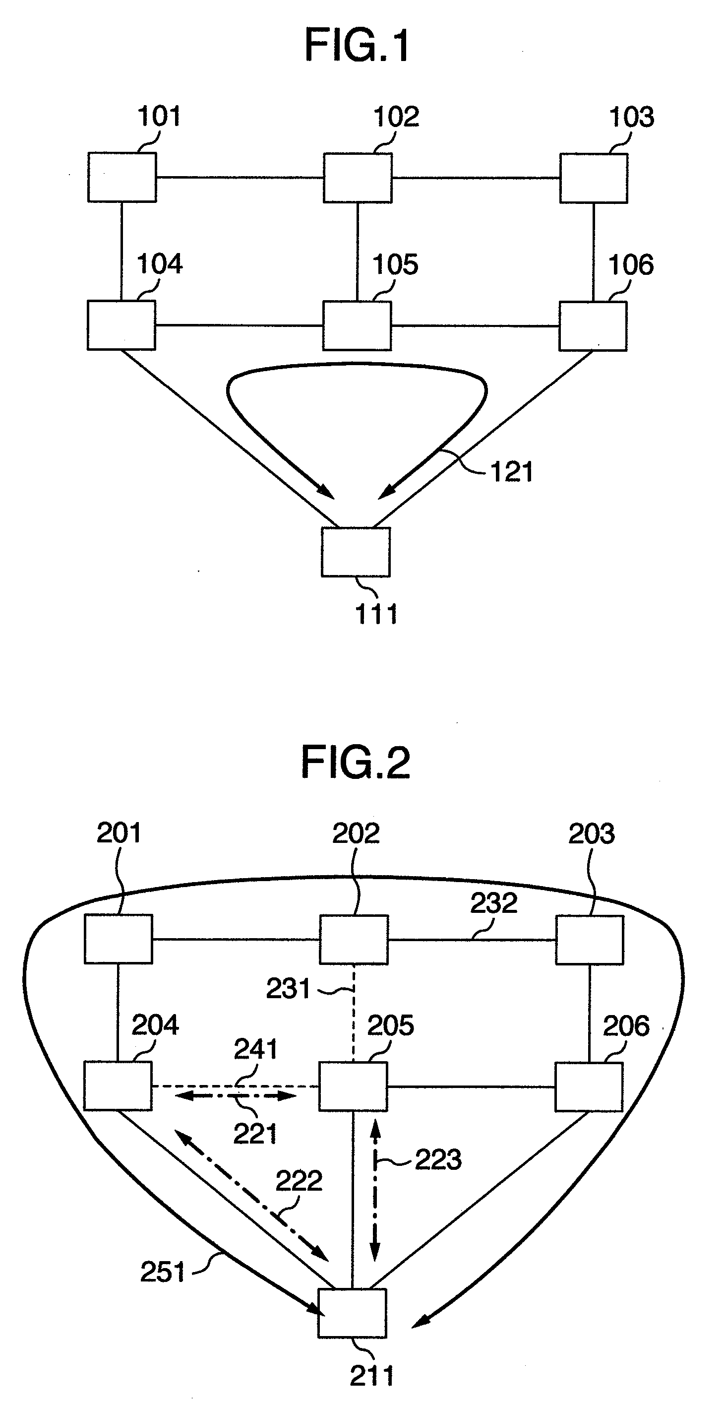
However, according to the above-described conventional techniques, if redundancy programs operate independently as in the case of the above-described edge networks and core network, even if a change in the communication route occurs in one redundancy program, this change is not notified to the other redundancy programs so that the MAC address learning results are not cleared and updated.
There arises a problem of a delay in communication recovery.
With this operation, the MAC address learning results are therefore not coincident with the actual network, posing a problem that communications cannot be recovered although the device 111 switched the communication route by its redundancy protocol.
It takes therefore a long time until communication recovery is established.
In contrast, the above-described conventional techniques adopt an approach to relaying a control packet via the core network, and waiting for time-out of a timer regarding the control packet because a failure of each line cannot be detected due to non-direct interconnections.
There arises therefore a problem of an abnormally longer time taken for switching the communication route.
In this case, during the period from when the core network is recovered to when the communication routes of the edge network are changed to the normal communication routes, the edge network continues to have a plurality of communication routes to the recovered core network, resulting in a problem that a loop of the whole network occurs temporarily.
In the method by which the devices in the core network for connecting the edge network operate the redundancy protocol of the edge network at the same time, in order to solve the problem that a line failure cannot be detected directly in the relay approach of the above-described techniques, the devices 204 and 205 are required to be connected directly, resulting in a problem that the network architecture has some restrictions so that a flexible network architecture is impossible.
There is another problem that a large loop riding over the control range of a plurality of redundancy protocols cannot be prevented if positions of blocking points for preventing a network loop in the redundancy protocols of the core and edge networks fall on the same line.
In addition, even if the positions of the blocking points of the redundancy protocols of the core and edge networks do not fall on the same line, if the blocking point of the redundancy protocol of the edge network is set to a line of the core network, this blocking point falls on a normal communication route of the core network, resulting in a problem of a loss of communication arrivability of the core network.
Since a failure or a change in the architecture propagates to the whole network, there arises a problem that a failure in a terminal device of a large scale network influences another remote terminal device irrelevant in terms of the architecture so that a load of each device in the whole network is increased, and a problem that since a change in the architecture such as addition of a device to the network influences the whole network, the architecture cannot be changed easily.

Method used


Image

  • Layer-2 Redundancy Protocol Interconnection Device
  • Layer-2 Redundancy Protocol Interconnection Device
  • Layer-2 Redundancy Protocol Interconnection Device

Examples


first embodiment

[0129]FIG. 9 shows an embodiment in which a ring network 901 as a higher level network under control of a ring protocol which is one of layer-2 redundancy protocols is connected to a spanning tree network 902 as a lower level network under control of a spanning tree protocol which is one of layer-2 redundancy protocols. The ring network as the higher level network is connected to the spanning tree network as the lower level network by interconnection devices 911 and 912. The spanning tree network is redundancy-connected to the ring network via two interconnection devices.

[0130]The ring network 901 constitutes a ring topology by devices 911, 912, 921 and 922 and lines 931 to 934. The ring protocol operates as the higher level protocol on the devices 921 and 922, and also on the interconnection devices 911 and 912 to control higher level ports 941 to 943. The ports under control transmit / receive the control packet of the ring protocol. Under control of the ring protocol, a blocking po...

second embodiment

[0147]The second embodiment shows a case wherein two or more lower level networks are connected to one higher level network.

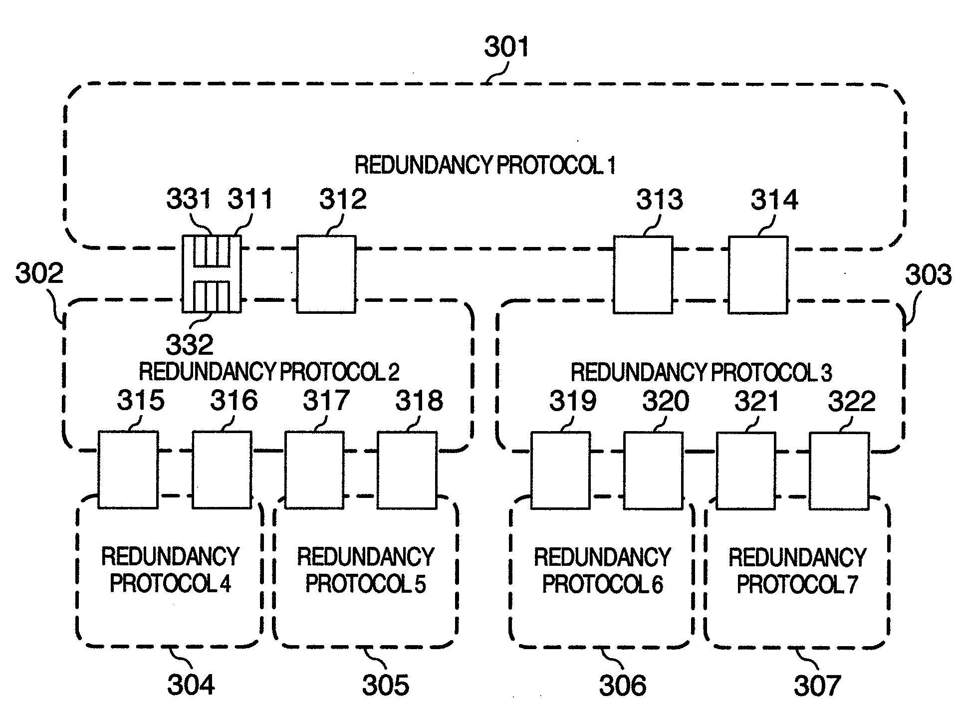
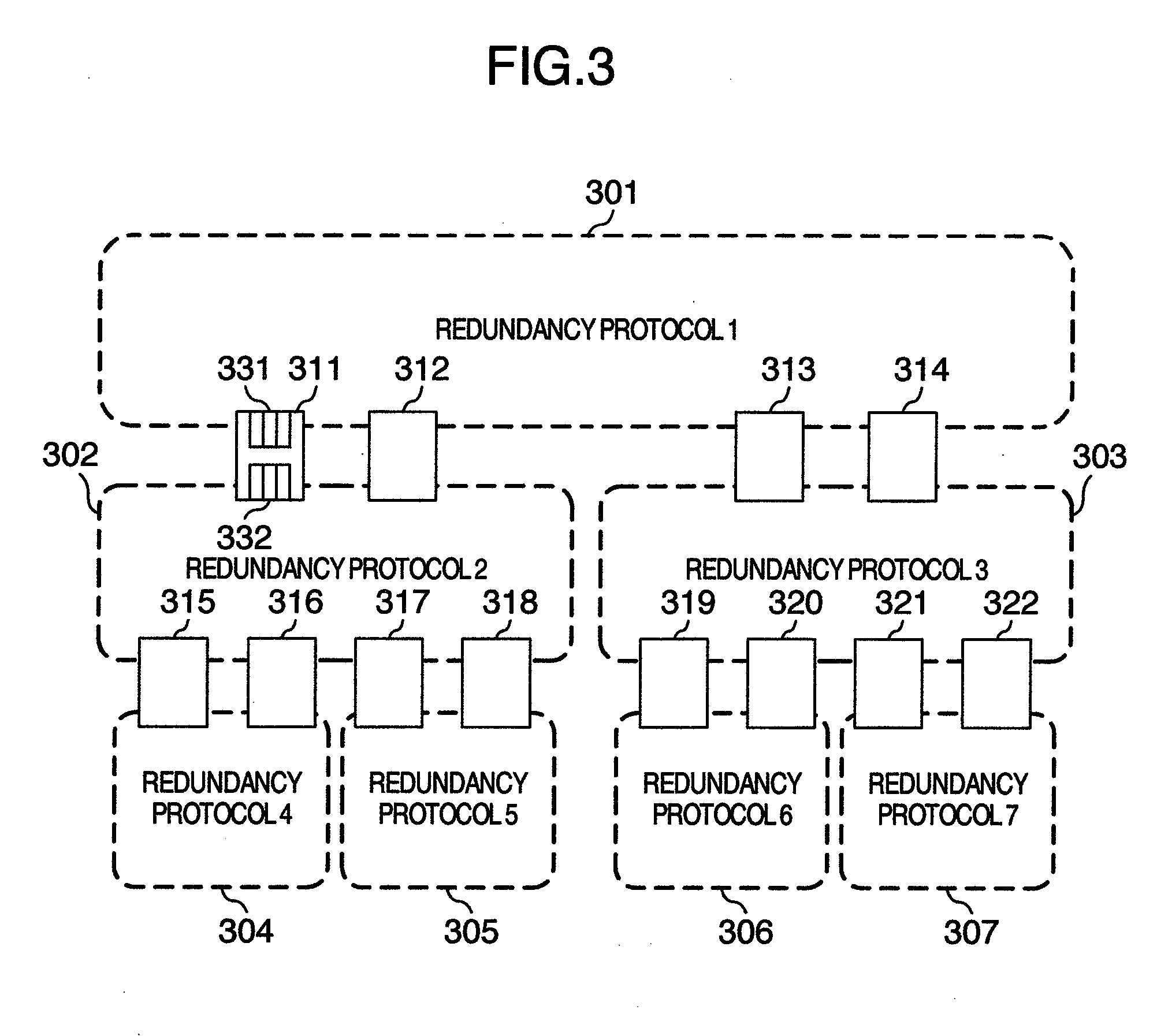
[0148]FIG. 13 shows an example adding one spanning tree network as the lower level network to the architecture of the first embodiment shown in FIG. 9. Spanning tree networks 1302 and 1303 as the lower level network are connected to a ring network 1301 as the higher level network. The spanning tree network 1302 is connected to the ring network 1301 by interconnection devices 1311 and 1312, whereas the spanning tree network 1303 is connected to the ring network 1301 by interconnection devices 1313 and 1314. The ring network is constituted of higher level ports 1331 and 1332 of the interconnection device 1311, higher level ports 1333 and 1334 of the interconnection device 1312, higher level ports 1335 and 1336 of the interconnection device 1313, and higher level ports 1337 and 1338 of the interconnection device 1314. Under control of the ring protocol, a blocking...

third embodiment

[0157]FIG. 15 shows an architecture in which three interconnection devices 1511 to 1513 are connected to a ring network 1501 as the higher level network, and three types of redundancy communication routes are prepared for a spanning tree network 1502 as the lower level network. The spanning tree protocol requires direct connections between ports in order to realize high speed switching. Therefore, two virtual ports are prepared for each interconnection device, interconnection devices 1511 and 1513 are connected by a virtual link 1551 via virtual ports 1541 and 1546, the interconnection devices 1511 and 1512 are connected by a virtual link 1552 via virtual ports 1542 and 1543, and the interconnection devices 1512 and 1513 are connected by a virtual link 1553 via virtual orts 1544 and 1545. Communications among the virtual links are made redundant by the ring network.

[0158]Under control of the ring protocol, a blocking point is set to a higher level port 1523 of the interconnection de...


PUM


Abstract

Interconnection devices and interconnect a network running a redundancy protocol and another network running a redundancy protocol. The interconnection devices controls the redundancy protocol of a lower level network via virtual ports and by a virtual link, to redundancy-connect the lower level network to a higher level network. When a communication route of the lower level network is changed, MAC address learning results of the higher level network are cleared to perform switching of communication routes at high speed.

Description

BACKGROUND OF THE INVENTION[0001]1. Field of the Invention[0002]The present invention relates to techniques of allowing a flexible network to be configured, by realizing simultaneous adoption of a plurality of redundancy protocols on one network, in order to adopt a redundancy protocol suitable for a network architecture of a network using a redundancy protocol providing redundancy of a communication route. The present invention relates also to techniques allowing localization of influence of switching of a communication route upon communications and devices to reduce a load on a network adopting a redundancy protocol, and realizing high speed switching of a communication route.[0003]2. Description of the Related Art[0004]When a network is configured, a redundancy protocol is used in some cases in order to realize redundancy of communication routes. There are various protocols for redundancy of communication routes: protocols employing a network architecture such as a mesh architect...

Claims


Application Information

Patent Timeline
IPC IPC(8): H04L12/24H04L45/24H04L45/18H04L45/247
CPCH04L45/00H04L45/48H04L45/28H04L45/18H04L45/76
Inventor NOZAKI, SHINJISAKURAI, HIROTO
Owner ALAXALA NETWORKS
Learn More