
Target marking system having a gas laser assembly and a thermal imager

a target marking and gas laser technology, applied in the field of target marking systems, can solve the problems of system failure to provide for a proactive approach to situational developments, and no system for actively marking targets,

Inactive Publication Date: 2009-04-30
LMD APPL SCI LLC
View PDF1 Cites 57 Cited by
  • Summary
  • Abstract
  • Description
  • Claims
  • Application Information

AI Technical Summary

Benefits of technology

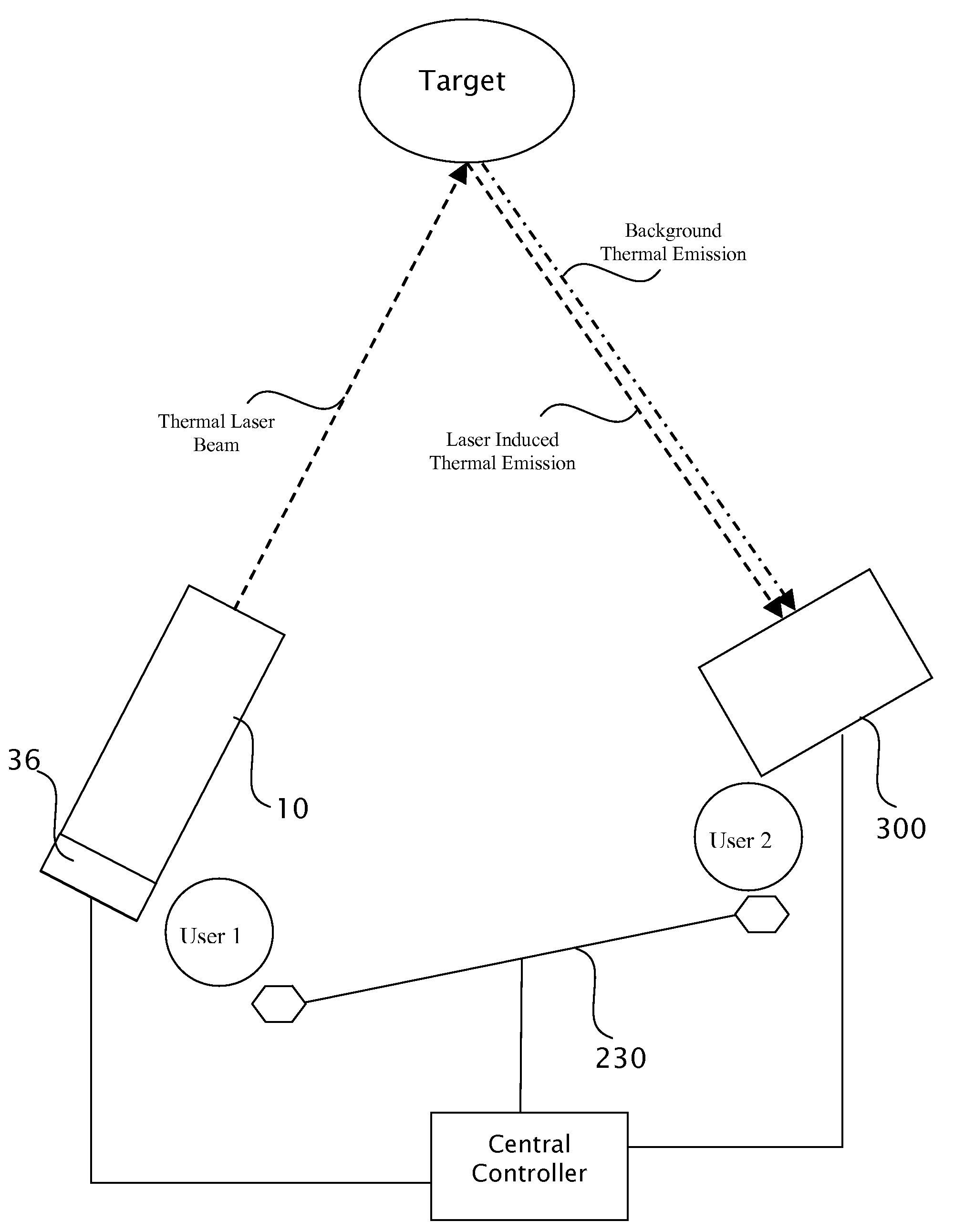
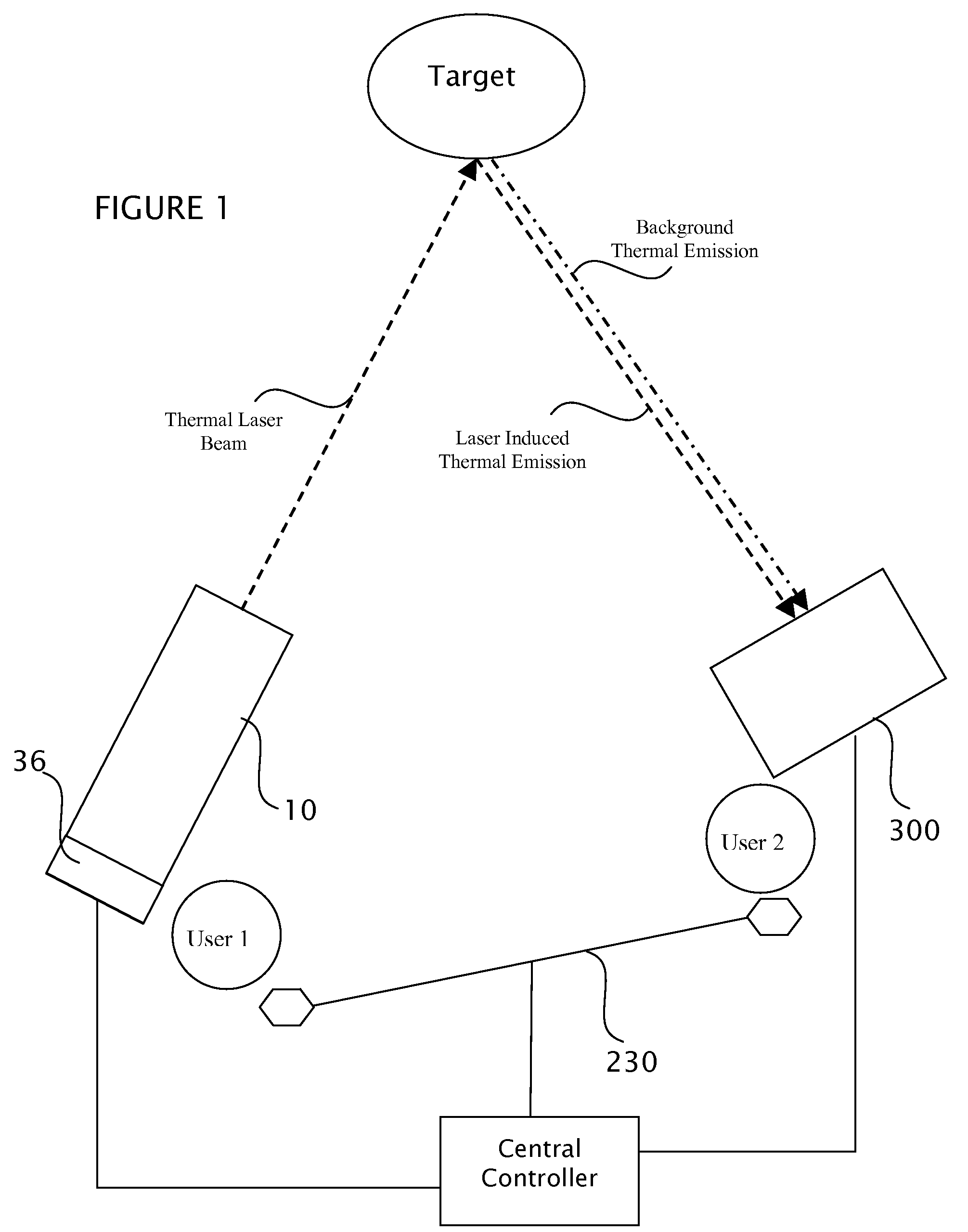
[0010]The present system includes a target marking system employing a portable or weapon-mounted target marker which can selectively create a beam of thermal infrared radiation. The beam can be either directly viewed by a thermal imager or can be used to induce a local temperature differential on the target which is viewable by the thermal imager. The target marker further provides for operation in a robust configuration for use at ambient temperatures found in field environments.

Problems solved by technology

Conversely, image intensifier or I2 technology do not detect the thermal emissions.
While these applications allow monitoring and imaging of otherwise invisible radiation, the systems do not provide for a proactive approach to situational developments.
No system exists for employing thermal imaging for actively marking targets.

Method used


Image

  • Target marking system having a gas laser assembly and a thermal imager
  • Target marking system having a gas laser assembly and a thermal imager
  • Target marking system having a gas laser assembly and a thermal imager

Examples


Embodiment Construction

[0020]Referring to FIG. 1, a target marking system includes a target marker 10 for use with a thermal imager 300. Although the target marker 10 is shown as a separate and independent construction from the thermal imager 300, it is contemplated the target marker can be cooperatively or integrally connected to the thermal imager. For purposes of description, the target marker 10 is set forth as a separate, remotely deployable device from the thermal imager 300.

[0021]The thermal imager 300 is known in the art and can be any of a variety of configurations. In the thermal imager 300, thermal infrared radiation, spanning the infrared range, preferably 7 to 14 microns, is captured and converted into a visible image. Objects with temperatures above 0° Kelvin emit light energy (black body radiation), a portion of which is in the thermal infrared spectrum. Thus, all objects above 0° K. are theoretically viewable by the thermal imager 300.

[0022]In one form of the thermal imager 300 (a micro-bo...


PUM


Abstract

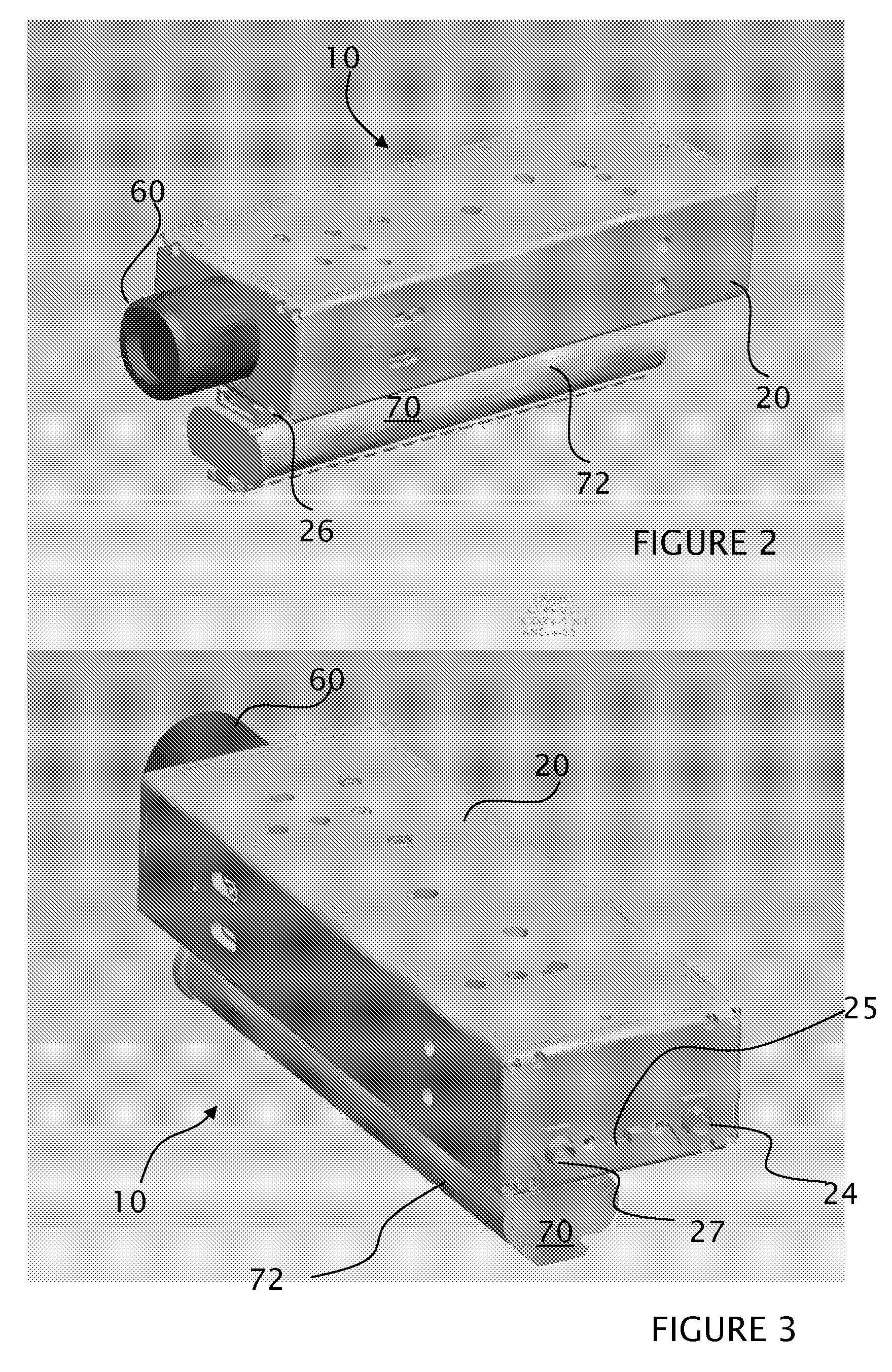
A handheld target marker is provided, wherein the target marker includes a housing retaining a gas laser, a collimating or focusing lens, a driver and a power supply. The laser produces a thermal infrared beam which can be selectively directed to impinge upon a target. The impinging beam is viewable by a thermal imager. The handheld target marker operates at ambient temperatures and incorporates the driver and power supply necessary for operation of the laser, wherein the beam can be pulsed for enhancing imaging on the thermal imager.

Description

CROSS-REFERENCE TO RELATED APPLICATIONS[0001]Not Applicable.STATEMENT REGARDING FEDERALLY SPONSORED RESEARCH OR DEVELOPMENT[0002]Not Applicable.REFERENCE TO A “SEQUENCE LISTING”[0003]Not Applicable.BACKGROUND OF THE INVENTION[0004]1. Field of the Invention[0005]The present invention relates to a target marking system, and more particularly, to a handheld or weapon mounted device incorporating a gas laser such as a carbon dioxide (CO2) or carbon monoxide (CO) laser for generating and impinging a thermal infrared beam upon a target to create a corresponding image in a thermal imager.[0006]2. Description of Related Art[0007]Thermal imagers operate in the mid- and long-wave infrared bands (3-5 micron and 8-12 micron, respectively). Ideal “black bodies” radiate in a spectral region determined by their temperature. “Grey bodies” emit similarly, but the spectral radiance is mediated by material properties. All real objects are grey bodies, and radiate in a manner that can be related to tem...

Claims


Application Information

Patent Timeline
IPC IPC(8): H01S3/22
CPCH01S3/10069F41G3/145F41G1/36H01S3/2232
Inventor HOUDE-WALTER, WILLIAM R.HOUDE-WALTER, SUSANMOCK, JEFFREYWOLINSKI, JEFFREYOLMSTED, BRIANGAGLIANO, CHRISTOPHER
Owner LMD APPL SCI LLC
Learn More