Moving picture prediction method, moving picture coding method and apparatus, and moving picture decoding method and apparatus

a prediction method and moving picture technology, applied in the field of moving picture prediction method, can solve the problems of large storage capacity large size of the calculation apparatus, and large weighting coefficient (quotient) size, so as to reduce the memory size of the look-up table and the like, reduce the storage capacity accompanying the scaling processing, and improve the efficiency of scaling processing

Inactive Publication Date: 2009-04-30
GK BRIDGE 1
View PDF14 Cites 12 Cited by
  • Summary
  • Abstract
  • Description
  • Claims
  • Application Information

AI Technical Summary

Benefits of technology

[0016]Additionally, it is another object of this invention to provide a moving picture prediction method and the like that enable the calculations in the prediction of a moving picture by the temporal scaling processing to be a small size without increasing the significant digit number necessary for the calculations.
[0025]As is apparent from the above explanation, the moving vector prediction method according to the present invention makes the scaling processing using two reference pictures more efficient. Hereby, the calculation amount and the storage capacity accompanying the scaling processing are reduced.
[0026]In other words, the memory size of the look-up table and the like is reduced. The look-up table stores the number of the reciprocal calculations and the reciprocals required to avoid the divisions for calculating the weighting coefficients in generation of predictive pixel values and motion vectors. Furthermore, the scaling processing is performed with a predetermined significant bit number (16 bits, for example), and enlargement of a circuit size is avoided.

Problems solved by technology

Further, there is another problem that large storage capacity of the look-up table and the like that store the reciprocals is necessary.
Moreover, when the denominators (the devisors of the weighting coefficients) in above-mentioned Formulas 1 and 2 become small, the weighting coefficients (the quotients) become extremely large and there is a problem, for example, that the predictive pixel values cross a value that can be expressed by 16 bits.
Therefore, for example, a 32-bit calculation becomes necessary and since the significant digit number necessary for the calculations increases, the size of a calculation apparatus becomes large.

Method used


Image

  • Moving picture prediction method, moving picture coding method and apparatus, and moving picture decoding method and apparatus
  • Moving picture prediction method, moving picture coding method and apparatus, and moving picture decoding method and apparatus
  • Moving picture prediction method, moving picture coding method and apparatus, and moving picture decoding method and apparatus

Examples


first embodiment

The First Embodiment

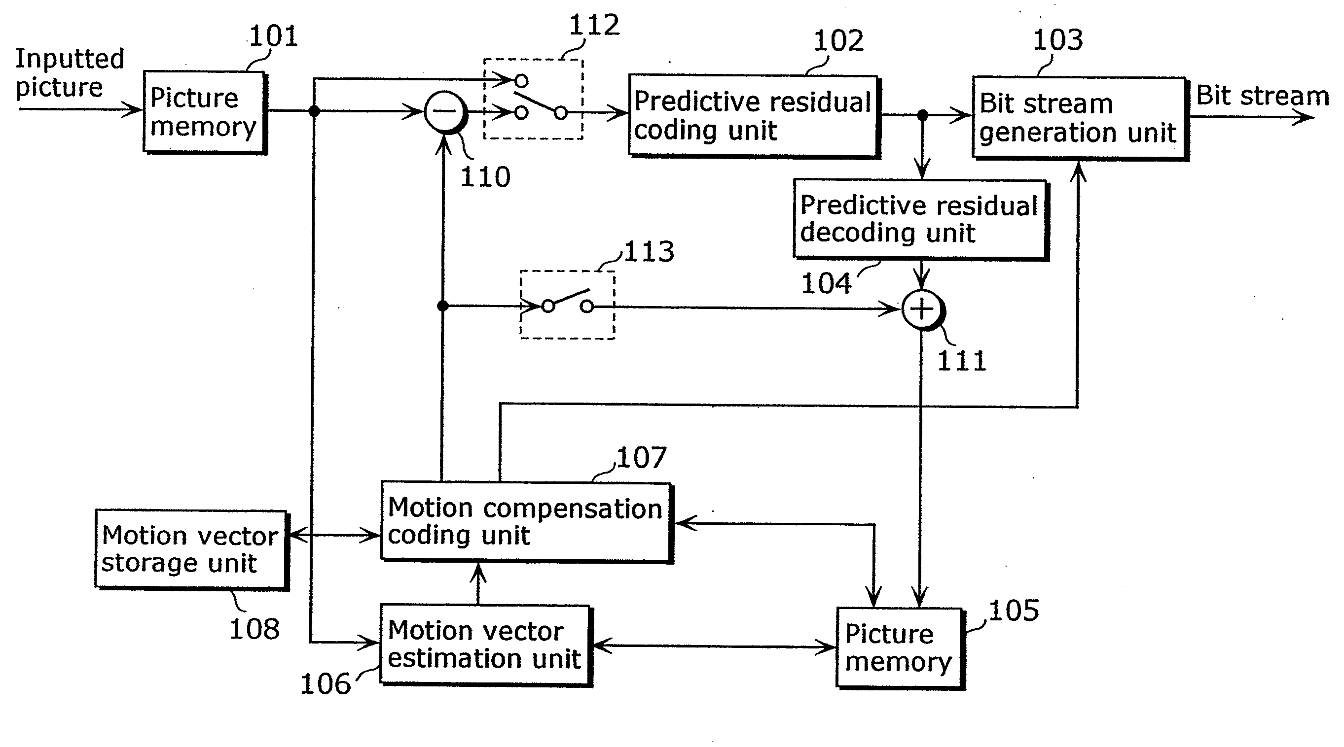
[0044]FIG. 5 is a block diagram showing the structure of the moving picture coding apparatus according to one embodiment using the moving picture prediction method according to the present invention.

[0045]The moving picture coding apparatus includes picture memory 101, a predictive residual coding unit 102, a bit stream generation unit 103, a predictive residual decoding unit 104, picture memory 105, a motion vector estimation unit 106, a motion compensation coding unit 107, a motion vector storage unit 108, a difference calculation unit 110, an addition calculation unit 111, a switch 112 and a switch 113.

[0046]The picture memory 101 stores moving pictures inputted picture-by-picture basis in display order. The motion vector estimation unit 106 uses coded decoding picture data as a reference picture and performs estimation of a motion vector that shows the position predicted to be optimum in the research area in the picture.

[0047]The motion compensation coding un...

second embodiment

The Second Embodiment

[0080]Next, the moving picture decoding apparatus using the moving picture prediction method according to the present invention is explained.

[0081]FIG. 11 is a block diagram showing the structure of the moving picture decoding apparatus according to one embodiment using the moving picture prediction method according to the present invention.

[0082]The moving picture decoding apparatus includes a bit stream analysis unit 201, a predictive residual decoding unit 202, picture memory 203, a motion compensation decoding unit 204, a motion vector storing unit 205, an addition calculation unit 207 and a switch 208.

[0083]The bit stream analysis unit 201 extracts various data such as coding mode information and motion vector information used at the time of coding from an inputted bit stream. The predictive residual decoding unit 202 performs decoding to inputted predictive residual coding data and generates predictive residual picture data.

[0084]The motion compensation de...

third embodiment

The Third Embodiment

[0092]Next, an example of realizing the moving picture prediction method, the moving picture coding apparatus and the moving picture decoding apparatus according to the present invention in another embodiment is explained.

[0093]It is possible to easily perform the processing shown in the above embodiments in an independent computing system by recording a program for realizing the structure of the picture coding apparatus or the picture decoding apparatus shown in the above-mentioned embodiments onto the storage medium such as a flexible disk.

[0094]FIG. 12 is an illustration for realizing the moving picture prediction method, the moving picture coding / decoding method using a flexible disk that stores a program for realizing the structure of the moving picture coding apparatus or the moving picture decoding apparatus.

[0095]FIG. 12B shows a full appearance of a flexible disk, its structure at cross section and the flexible disk itself whereas FIG. 12A shows an examp...


PUM


Abstract

A moving picture prediction method for enabling a calculation amount and a storage capacity to be reduced in a prediction about a moving picture by scaling processing is provided. A method for predicting the value P of Time T from the value P0 of Time T0 and the value P1 of Time T1 includes a step of judging whether it is possible to generate a predictive value with a predetermined significant number of bits by scaling using Time T0, T1 and T (Step S90); a step of predicting the value P from the values P0 and P1 by scaling using Time T0, T1 and T when it is possible to generate a predictive value with the predetermined significant number of bits (Step S92); and a step of predicting the value P from the values P0 and P1 without using Time T0, T1 and T when it is impossible to generate a predictive value with the predetermined significant number of bits (Step S91).

Description

TECHNICAL FIELD[0001]The present invention relates to a prediction method of a pixel value in a moving picture, and particularly to a prediction method for performing temporally scaling processing based on two pictures.BACKGROUND ART[0002]Generally in moving picture coding, the amount of information is compressed using redundancy in spatial direction and temporal direction that a moving picture has. There is inter picture prediction coding as a method for using the redundancy in temporal direction. In the inter picture prediction coding, a temporary preceding picture or a temporary subsequent picture is used as a reference picture when a picture is coded. Then, motion amount is detected from the reference picture and the amount of information is compressed by removing redundancy in spatial direction toward a difference value between a picture to which motion compensation is performed and a picture to be coded.[0003]In such a moving picture coding method, a picture that does not perf...

Claims


Application Information

Patent Timeline
Patent Type & Authority Applications(United States)
IPC IPC(8): H04N7/12H04N11/02H04N19/50H04N19/105H04N19/134H04N19/159H04N19/189H04N19/196H04N19/423H04N19/426H04N19/46H04N19/503H04N19/51H04N19/513H04N19/60H04N19/61H04N19/70H04N19/91
CPCH04N19/114H04N19/00024H04N19/00072H04N19/00266H04N19/00575H04N19/119H04N19/182H04N19/105H04N19/503H04N19/172H04N19/577H04N19/00721H04N19/51H04N19/176H04N19/31
Inventor KADONO, SHINYALIM, CHONG SOONFOO, TECK WEESHEN, SHENG MEI
Owner GK BRIDGE 1
Why Eureka
Try Eureka