
Method of modifying pilot power for a home base station router based on user demand

a router and pilot power technology, applied in the field of wireless communication systems, can solve the problems of large number of femtocells, increase the signaling overhead of the wireless communication network, and disrupt the careful cell planning and optimization

Inactive Publication Date: 2009-04-30
LUCENT TECH INC
View PDF14 Cites 156 Cited by
  • Summary
  • Abstract
  • Description
  • Claims
  • Application Information

AI Technical Summary

Benefits of technology

[0010]The present invention is directed to addressing the effects of one or more of the problems set forth above. The following presents a simplified summary of the invention in order to provide a basic understanding of some aspects of the invention. This summary is not an exhaustive overview of the invention. It is not intended to identify key or critical elements of the invention or to delineate the scope of the invention. Its sole purpose is to present some concepts in a simplified form as a prelude to the more detailed description that is discussed later.

Problems solved by technology

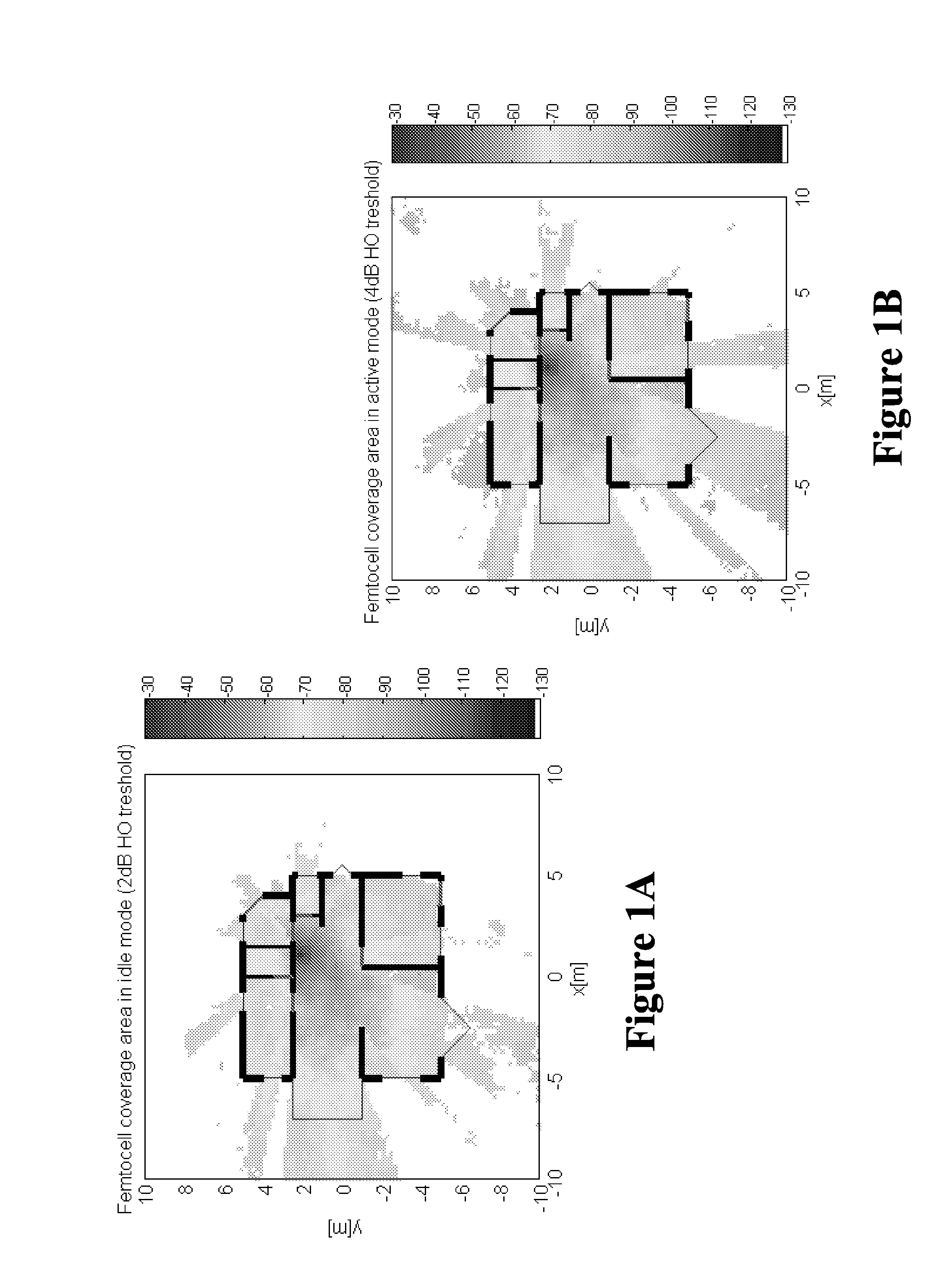
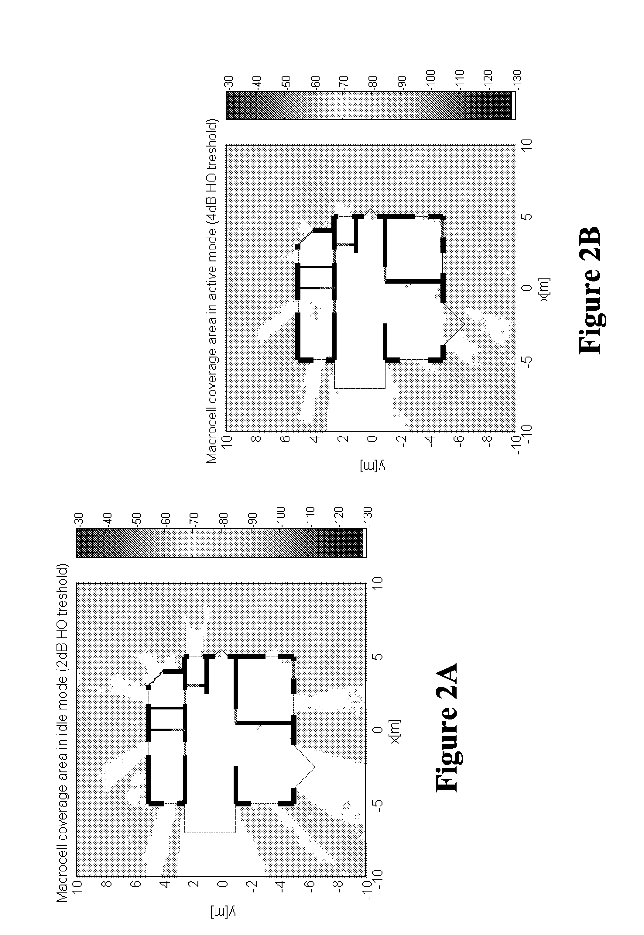
Deployment of home base station routers may result in a very large number of femtocells, which may overlap with or be encompassed by one or more macro-cells.
The presence of the femtocells may disrupt the careful cell planning and optimization used to configure the macro-cells.
Consequently, the presence of a large number of femtocells may undesirably increase the signaling overhead of the wireless communication network.
However, this approach would be very costly and run contrary to the goal of making home base station routers function as plug-and-play devices.
However this solves the problem only partially since for a typical house it is not possible to select the pilot such that it covers the whole house without spillage out of the windows.
Shadowing by obstacles such as walls also decreases the signal strength.

Method used


Image

  • Method of modifying pilot power for a home base station router based on user demand
  • Method of modifying pilot power for a home base station router based on user demand
  • Method of modifying pilot power for a home base station router based on user demand

Examples


Embodiment Construction

[0021]Illustrative embodiments of the invention are described below. In the interest of clarity, not all features of an actual implementation are described in this specification. It will of course be appreciated that in the development of any such actual embodiment, numerous implementation-specific decisions should be made to achieve the developers' specific goals, such as compliance with system-related and business-related constraints, which will vary from one implementation to another. Moreover, it will be appreciated that such a development effort might be complex and time-consuming, but would nevertheless be a routine undertaking for those of ordinary skill in the art having the benefit of this disclosure.

[0022]Portions of the present invention and corresponding detailed description are presented in terms of software, or algorithms and symbolic representations of operations on data bits within a computer memory. These descriptions and representations are the ones by which those ...


PUM


Abstract

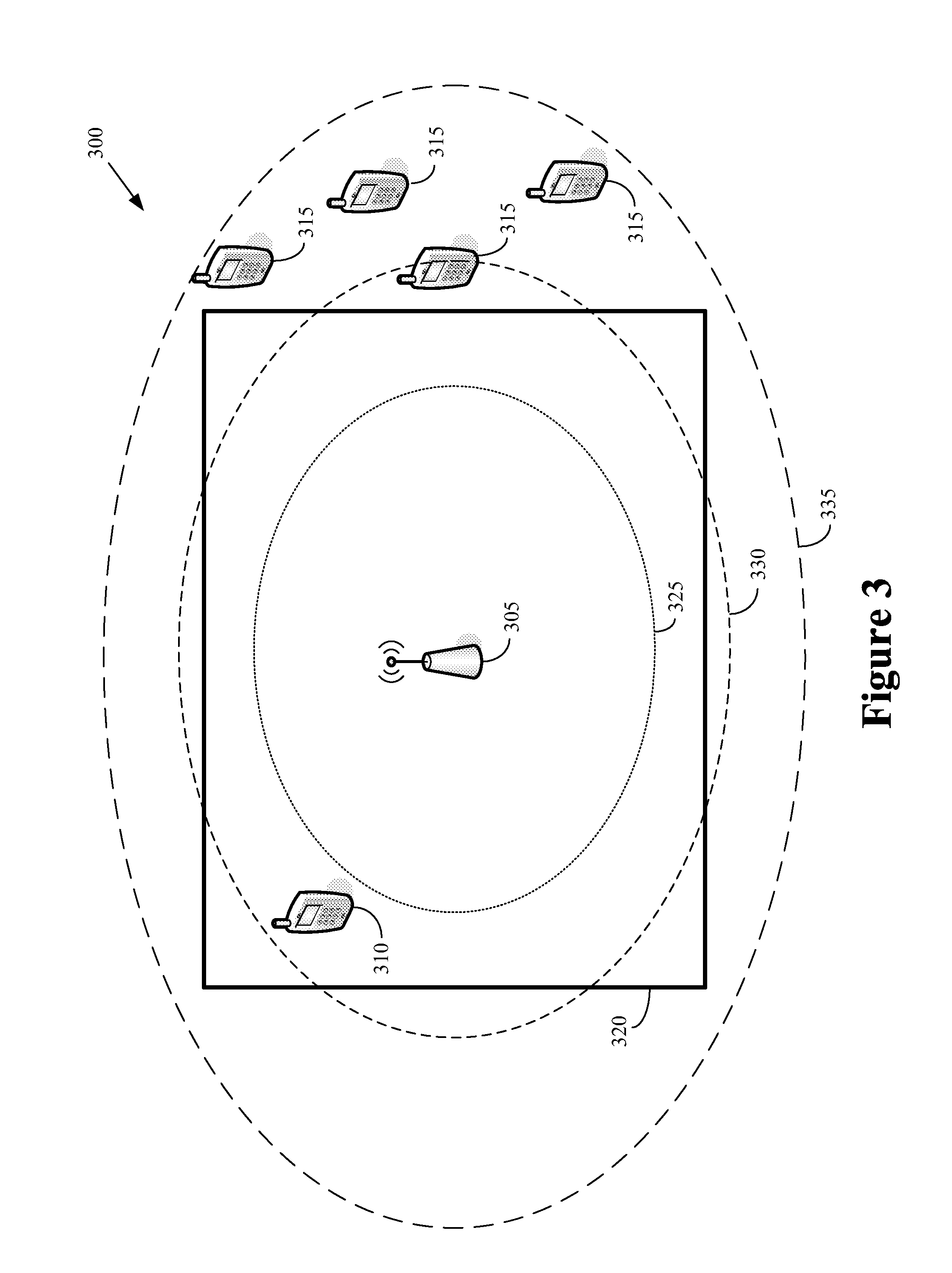
The present invention provides a method implemented in a base station router. One embodiment of the method includes determining a transmission power for a pilot signal transmitted by the base station router. The transmission power being determined based upon a number of mobile units that are camped on the base station router. Another embodiment of the method includes deploying the first base station router in a physical structure and estimating the dimensions of the physical structure based on a statistical representation of at least one handover attempt associated with the first base station router. Estimation of the dimensions of the physical structure occurs in response to deployment of the first base station router in the physical structure.

Description

CROSS REFERENCE TO RELATED APPLICATIONS[0001]This application is related to “U.S. patent application Ser. No. 11 / 771,644, entitled “Method of Automatically Configuring a Home Base Station Router” filed on 29th Jun., 2007, herein incorporated by reference in its entirety for all purposes.”BACKGROUND OF THE INVENTION[0002]1. Field of the Invention[0003]This invention relates generally to communication systems, and, more particularly, to wireless communication systems.[0004]2. Description of the Related Art[0005]Conventional wireless communication systems use a network of base stations to provide wireless connectivity to one or more mobile units. In some cases, the mobile units may initiate wireless communication with one or more base stations in the network, e.g., when the user of the mobile unit would like to initiate a voice or data call. Alternatively, the network may initiate the wireless communication link with the mobile unit. For example, in conventional hierarchical wireless c...

Claims


Application Information

Patent Timeline
Patent Type & Authority Applications(United States)
IPC IPC(8): H04Q7/30
CPCH04W36/16H04W36/30H04W52/242H04W84/045H04W52/325H04W52/343H04W52/367H04W52/287
Inventor BOSCH, PETERCLAUSSEN, HOLGERHO, LESTER T.W.SAMUEL, LOUIS G.
Owner LUCENT TECH INC
Learn More