Ultrasonic imaging apparatus

an ultrasonic imaging and ultrasonic technology, applied in the field of can solve the problems of unquantified evaluation of the divided frequency band, unsolved problems for further optimizing parameters for frequency compound imaging, etc., and achieve the effect of optimizing parameters

Inactive Publication Date: 2009-04-30
HITACHI LTD
View PDF2 Cites 7 Cited by
  • Summary
  • Abstract
  • Description
  • Claims
  • Application Information

AI Technical Summary

Benefits of technology

[0011]According to the present invention, it is possible to provide an ultrasonic

Problems solved by technology

However, in the above-described conventional techniques, when a frequency band is divided into any number of divided frequency bands, or into divided frequency bands with any intervals, optimal values

Method used


Image

  • Ultrasonic imaging apparatus
  • Ultrasonic imaging apparatus
  • Ultrasonic imaging apparatus

Examples


case 3

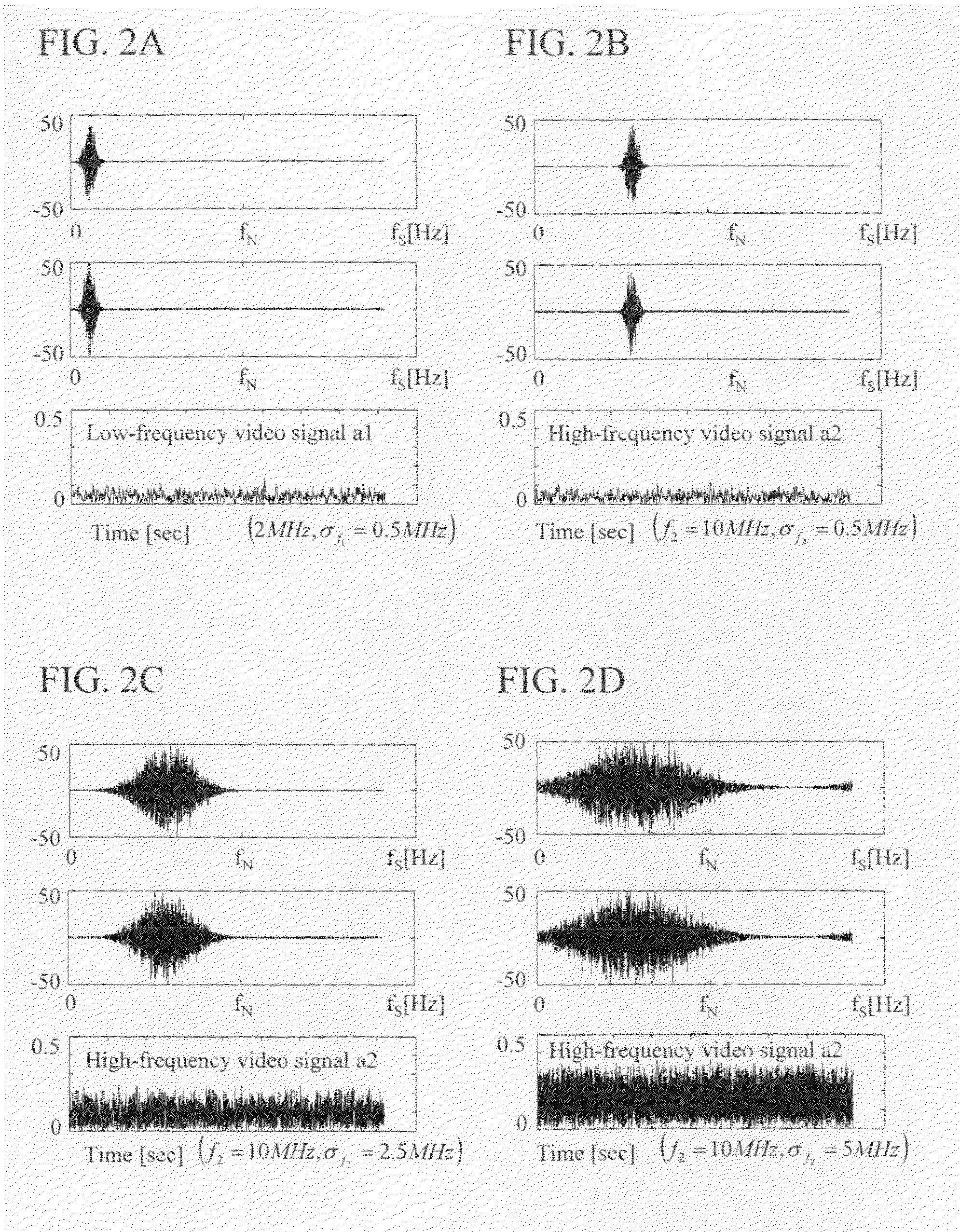
[0056] σf2>σf1˜σf3: f2: close to adjacent band having narrow width

(9) Estimation of Error

[0057]A relationship between an error in optimal setting and degree of deterioration in SSNR will be described as follows. Theoretically, SSNR is expressed by an average μ of ci√σi and dispersion σ as shown in the following equation based on the definition of SSNR.

μ=∑i=1nciσiσ2=∑i=1n{(ciσi)2-μ}2SSNR=n1+(σμ)2

[0058]As a result, a condition for obtaining SSNR of p√n or more can be given as follows.

σ / μ≦(1−p2) / p2)0.5

In the case of p=0.8, σ / μ≦0.5 is established. Moreover, this result is proved by the following numeral simulation.

[0059]In a case where the addition coefficient ci was shifted from the optimal setting, a reduced amount of SSNR was evaluated using the relationship between (c2 / c1) and (SSNR1+2 / SSNR1) (curve 401 in FIG. 3A, that is, curve 401 in FIG. 4) obtained when (σ2 / σ1) was determined. A range 501 of (c2 / c1), where a decrease of 20% from the maximum value of SSNR was allowed, and a ran...


PUM


Abstract

There is provided an ultrasonic imaging apparatus capable of optimizing parameters in frequency compound imaging. The ultrasonic imaging apparatus includes an optimal parameter calculation unit that calculates optimal values of processing parameters in the frequency compound imaging, and the optimal parameter calculation unit outputs a result that satisfies c1√σ1=c2√σ2= . . . cn√σn where the number of divided frequency bands is n, a bandwidth of a divided signal is σi and a signal intensity at the time of addition is ci (i=1, 2, . . . , n).

Description

CLAIM OF PRIORITY[0001]The present application claims priority from Japanese patent application JP 2007-278021 filed on Oct. 25, 2007, the content of which is hereby incorporated by reference into this application.BACKGROUND OF THE INVENTION[0002]1. Field of the Invention[0003]The present invention relates to a medical ultrasonic imaging apparatus, and more particularly relates to optimization of parameters for frequency compound imaging.[0004]2. Description of the Related Art[0005]Compounding smoothes speckles by averaging and adding signals in a plurality of directions to improve quality of vision of a minute contrast difference in an image. Particularly, in frequency compound imaging, a low frequency component and a high frequency component are subjected to signal processing, and added to thereby improve azimuth resolution itself and uniformity of resolution over an image of interest.[0006]Regarding the conventional frequency compound imaging, there is disclosed a study of a quan...

Claims


Application Information

Patent Timeline
IPC IPC(8): A61B8/14
CPCG01S7/52039G01S7/52038G01S15/895G01S7/52046
Inventor YAMAMOTO, MARIKO
Owner HITACHI LTD
Why Eureka
Try Eureka