Ultrasonic probe, charger, ultrasonic diagnostic apparatus and ultrasonic diagnostic system

a technology of ultrasonic diagnostic equipment and ultrasonic probe, which is applied in the direction of ultrasonic/sonic/infrasonic diagnostic equipment, transportation and packaging, tomography, etc., can solve the problems of inefficiency of battery charging and inability to use, and achieve the effect of efficient charging, short time, and efficient charging

Active Publication Date: 2009-04-30
KONICA MINOLTA INC
View PDF1 Cites 37 Cited by
  • Summary
  • Abstract
  • Description
  • Claims
  • Application Information

AI Technical Summary

Benefits of technology

[0048]According to the ultrasonic probe and charger according to the present invention, when the ultrasonic probe is connected to the charger, the transmitting and receiving operations of the ultrasonic waves can be automatically stopped, or the communication of the signal related to the transmission and reception of the transducer can be disconnected from the outside. Thus, the ultrasonic probe connected to the charger can be charged efficiently in a short time.
[0049]Also, according to the ultrasonic diagnostic apparatus and ultrasonic diagnostic system according to the present invention, when the operator removes the ultrasonic probe used for the diagnosis from the charger, only its ultrasonic probe executes the transmissi

Problems solved by technology

However, since the cordless ultrasonic probe described in the patent document 1 operates using the secondary battery as the power source, unless

Method used


Image

  • Ultrasonic probe, charger, ultrasonic diagnostic apparatus and ultrasonic diagnostic system
  • Ultrasonic probe, charger, ultrasonic diagnostic apparatus and ultrasonic diagnostic system
  • Ultrasonic probe, charger, ultrasonic diagnostic apparatus and ultrasonic diagnostic system

Examples


first embodiment

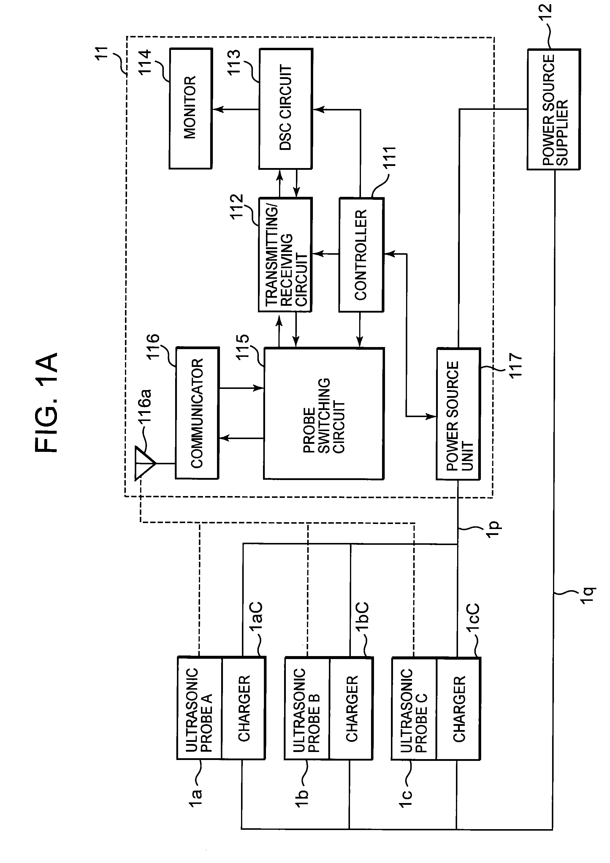
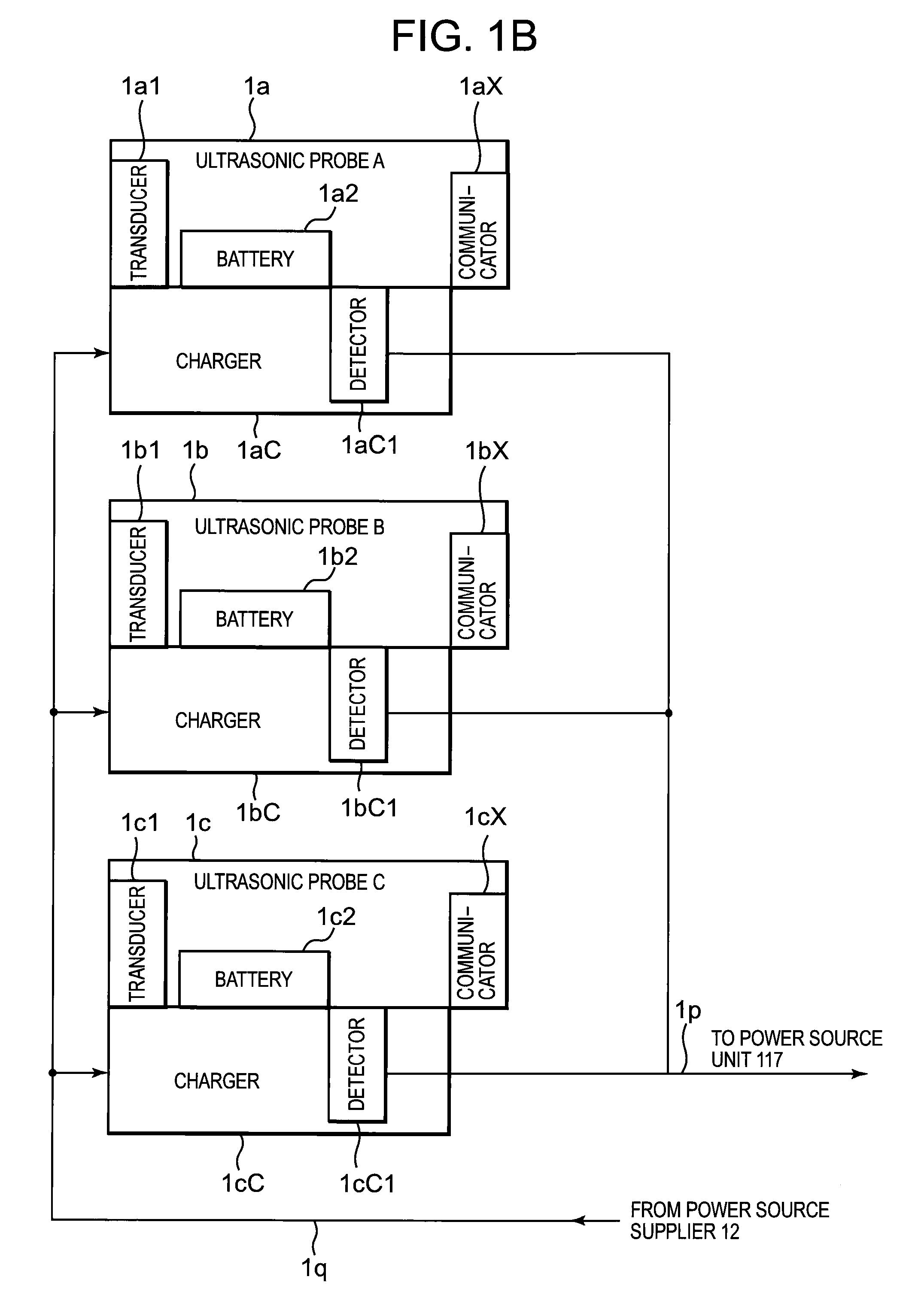
[0062]FIG. 1A is a block diagram showing the schematic configuration of the first embodiment of the ultrasonic diagnostic system according to the present invention, and FIG. 1B is a partially detailed block diagram showing the detailed content of the set of the three ultrasonic probes and chargers in FIG. 1A. In FIGS. 1A and 1B, wireless (cordless) ultrasonic probes 1a, 1b and 1c (although three ultrasonic probes are shown here, four or more ultrasonic probes may be used) for ultrasonic transmission and reception are arranged in an ultrasonic diagnostic apparatus 11 (hereafter, the ultrasonic probes 1a, 1b and 1c are also referred to as ultrasonic probes A, B and C, respectively). The ultrasonic probes 1a, 1b and 1c use rechargeable batteries 1a, 1b1 and 1c2 as operational power sources, respectively, and contain: transducers 1a1, 1b1 and 1c1 for executing transmitting and receiving operations for the ultrasonic waves; and communicators 1aX, 1bX and 1cX for wirelessly communicating ...

second embodiment

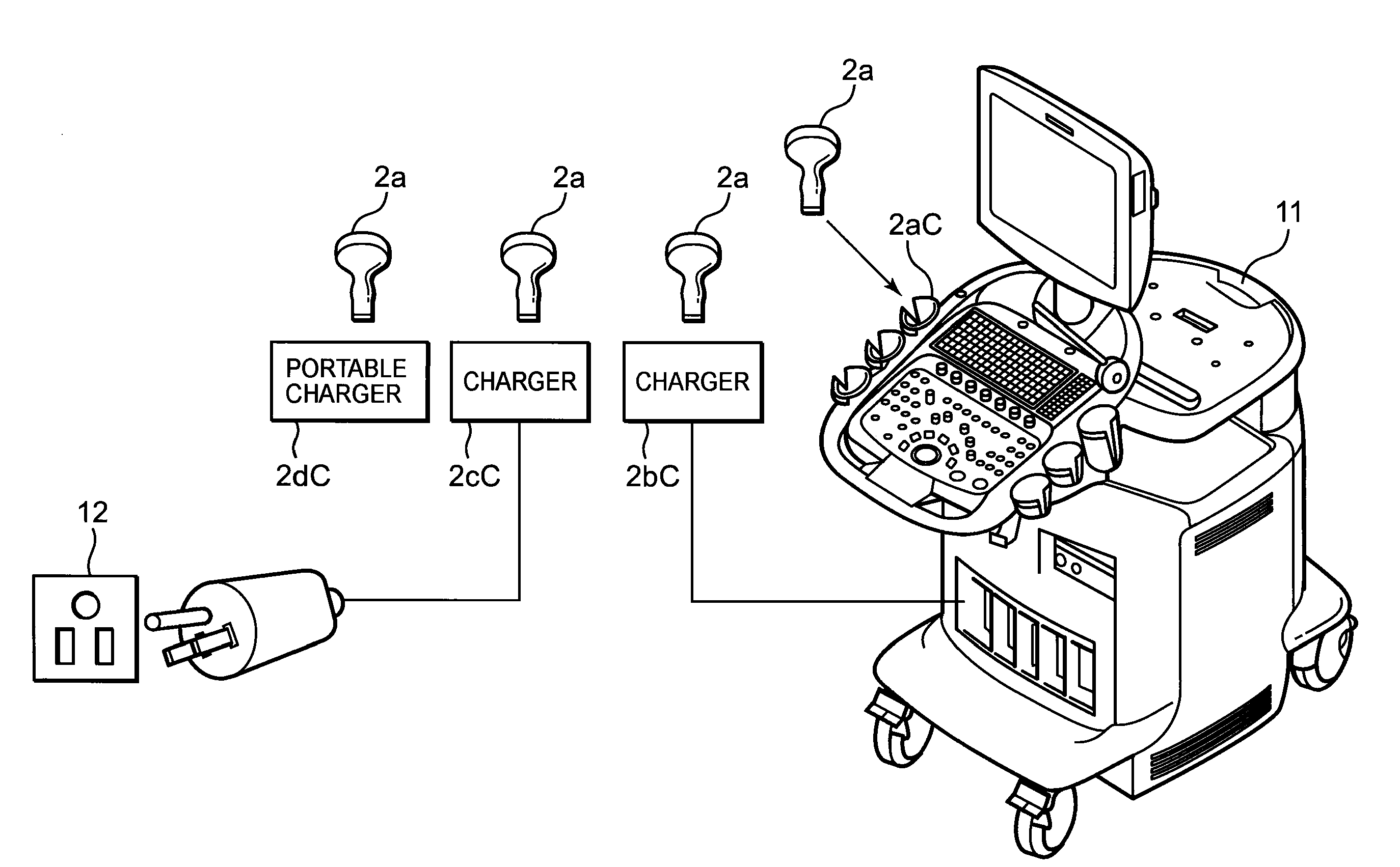
[0079]FIG. 2 is a perspective view showing the schematic configuration of the second embodiment of the ultrasonic diagnostic system according to the present invention, and exemplifies a case in which as compared with the ultrasonic diagnostic apparatus 11 shown in FIG. 1A, four wireless ultrasonic probes 2a are arranged as essential elements, and those ultrasonic probes 2a are connected to chargers 2aC, 2bC, 2cC and 2dC whose configurations differ from each other. So, the respective chargers 2aC, 2bC, 2cC and 2dC will be described below.

[0080]The charger 2aC is shown as a component integrated with the ultrasonic diagnostic apparatus 11. For example, the component in which the function of the charger is added to a probe holder is considered. The charger 2bC is shown as a component that is connected to the power source unit 117 (see FIG. 1A) in the ultrasonic diagnostic apparatus 11 by using a cable and the like is shown. This configuration eliminates the necessity of arranging the ch...

third embodiment

[0084]FIG. 7 is a perspective view showing the schematic configuration of the third embodiment in the ultrasonic diagnostic system according to the present invention. For example, a portable ultrasonic diagnostic apparatus 71 such as a notebook personal computer is used. Since the portable ultrasonic diagnostic apparatus 71 shown in FIG. 7 is small in size, it is difficult to reserve a position at which a conventional probe connector is to be mounted, and there is a limit of the size of the battery. For this reason, as the ultrasonic probe combined with the portable ultrasonic diagnostic apparatus 71, the development of the wireless ultrasonic probe 2a in which the battery of the charging type is built is requested. As this portable ultrasonic diagnostic apparatus 71 and the wireless ultrasonic probe 2a become popular, the use region of the ultrasonic diagnosis may extend more and more, without regard to inside or outside a hospital or the like. This third embodiment is very effecti...


PUM


Abstract

An ultrasonic probe that can be efficiently charged in a short time, a charger and an ultrasonic diagnostic apparatus, as well as an ultrasonic diagnostic system that uses them are provided by the present invention, which comprises a detector for detecting whether or not an ultrasonic probe having a rechargeable battery or the charger for charging this is in charging state; and a controller for stopping transmitting and receiving operations of ultrasonic waves. The ultrasonic diagnostic apparatus comprises a transmitting and receiving circuit for executing the generation of a signal related to the transmission of the ultrasonic waves and the generation of the diagnostic information based on the signal related to the reception of the ultrasonic waves; a probe switching circuit for selecting one of a plurality of ultrasonic probes; and a controller for controlling the probe switching circuit in accordance with a detection signal from the detector. The ultrasonic diagnostic system comprises the above-mentioned ultrasonic probes, chargers and ultrasonic diagnostic apparatus.

Description

TECHNICAL FIELD[0001]The present invention relates to a cordless ultrasonic probe that uses a rechargeable battery, a charger for charging this ultrasonic probe, an ultrasonic diagnostic apparatus for switching and using a plurality of ultrasonic probes, and an ultrasonic diagnostic system including them.BACKGROUND ART[0002]In ultrasonic diagnosis, ultrasonic waves are transmitted into a diagnosis target, and an echo signal thereof is received, thereby obtaining various kinds of diagnostic pieces of information such as the tomogram of the diagnostic target and the like. Although the transmission and reception of the ultrasonic waves were executed through an ultrasonic probe, the conventional ultrasonic probe was configured to be connected through a cable to an ultrasonic diagnostic apparatus (in this specification, an ultrasonic diagnostic apparatus body is referred to as an ultrasonic diagnostic apparatus, and a system that includes the ultrasonic probe and the ultrasonic diagnosti...

Claims


Application Information

Patent Timeline
IPC IPC(8): A61B8/14H02J7/00
CPCA61B8/00A61B8/4472A61B8/56H02J7/025A61B2560/0214A61B8/4209A61B8/44A61B8/4405A61B8/4444A61B8/4477H02J7/00034H02J2310/23H02J7/02H02J50/10
Inventor KUROKAWA, SHINYA
Owner KONICA MINOLTA INC
Why Eureka
Try Eureka