
Manipulator apparatus and medical device system

a technology of manipulator and medical device, which is applied in the direction of program control, surgical forceps, instruments, etc., can solve the problems of poor operability of the distal end portion, increased driving error, and poor operation of the treatment instrument which passes through the forceps channel of the endoscope, and achieves high accuracy and high efficiency.

Active Publication Date: 2009-04-30
OLYMPUS CORP
View PDF14 Cites 45 Cited by
  • Summary
  • Abstract
  • Description
  • Claims
  • Application Information

AI Technical Summary

Benefits of technology

[0010]It is an object of present invention to provide a manipulator apparatus having a plurality of joints which are driven with high accuracy and high efficiency, and a medical device system equipped with the manipulator apparatus.

Problems solved by technology

When, in the calculation of joint angle trajectories, the number of joints to be driven is large, overall driving error increases due to the compounding of errors at each joint.
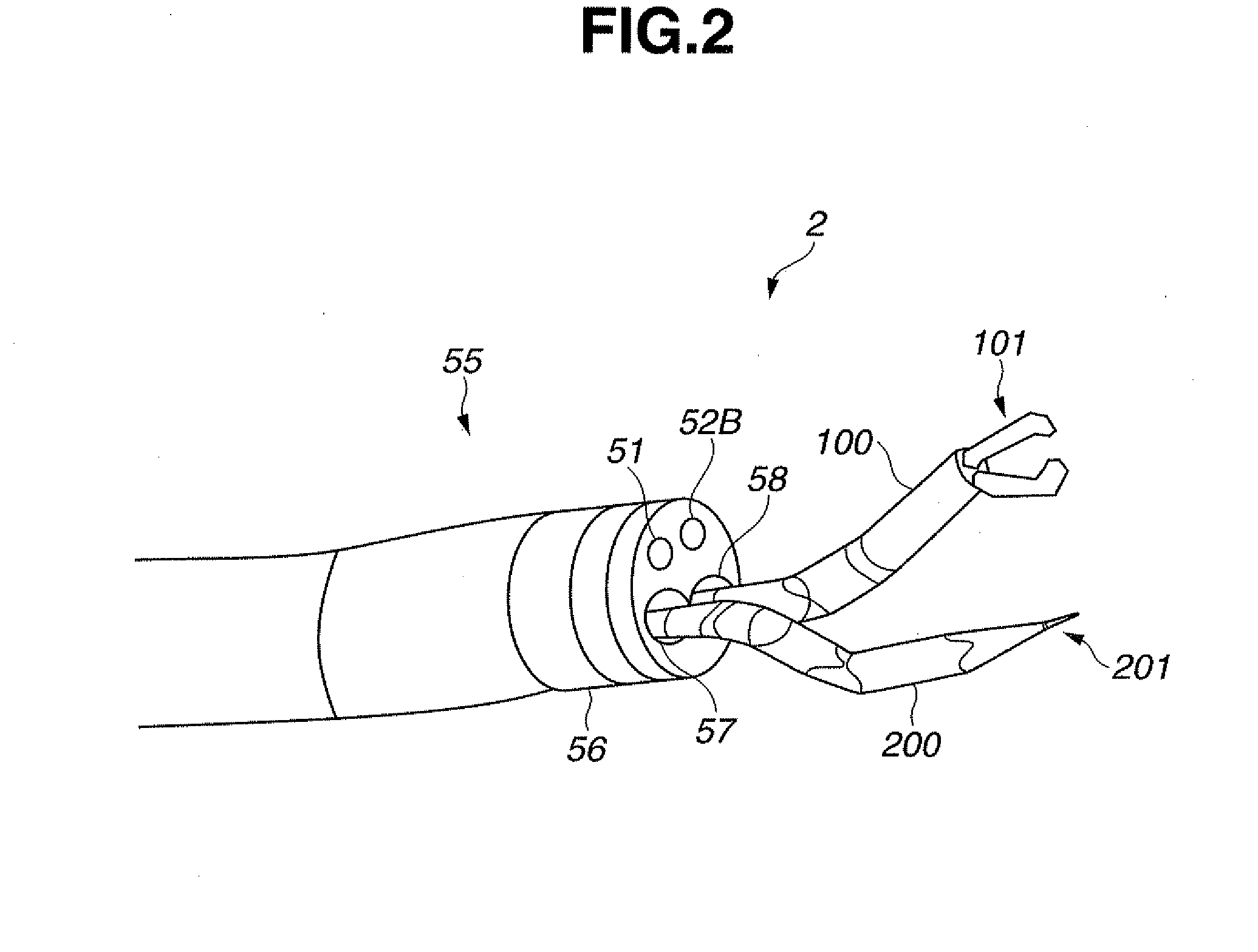
However, a treatment instrument which passes through the forceps channel of the endoscope and projects from distal end portion has poor operability, and so methods which make use of a miniature manipulator to increase the number of degrees of freedom and capabilities of the treatment instrument have been considered.
Although it is difficult for such a miniature manipulator which projects from the distal end portion to have a complex structure due to size constraints, high levels of accuracy and efficiency are demanded.
However, with this type of miniature manipulator apparatus, it is difficult to achieve both high accuracy and high efficiency.

Method used


Image

  • Manipulator apparatus and medical device system
  • Manipulator apparatus and medical device system
  • Manipulator apparatus and medical device system

Examples


Embodiment Construction

[0023]The following describes embodiments of the invention with reference to the accompanying drawings.

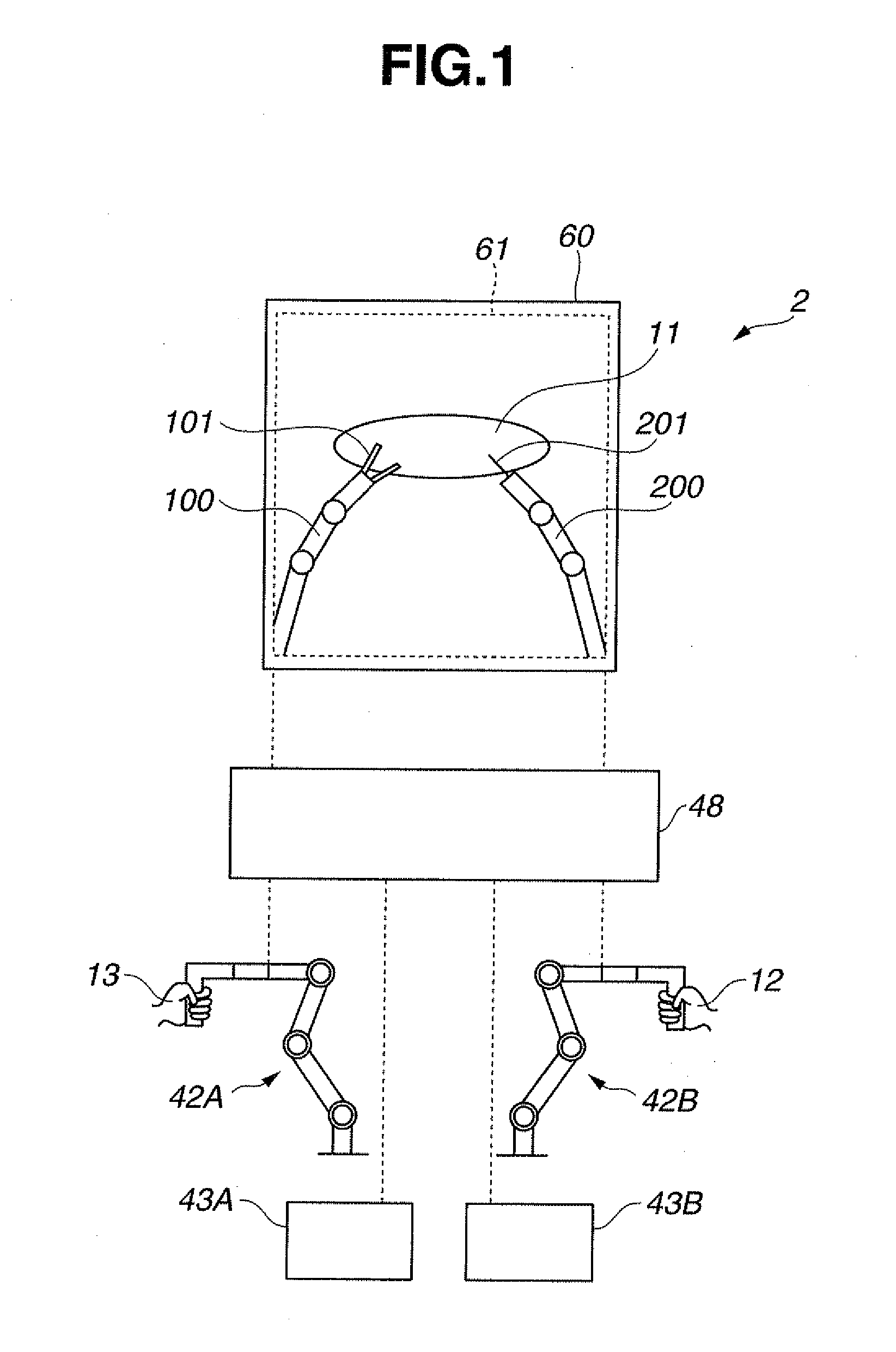
[0024]FIG. 1 is a schematic view for explaining an outline of a medical device system 2 of an embodiment of the invention. In FIG. 1, a display screen of a display apparatus 60, which is a display portion, displays a pickup image 61 of inside a living body 10 picked up using a CCD 51, which is an image pickup portion, of the endoscope apparatus 50 which is described in a later section. The pickup image 61 includes manipulators 100 and 200, each of which has two joints, for performing treatment on a diseased portion 11 within the living body 10. A hand arm is provided at a distal end portion 101 of the manipulator 100, and a knife arm is provided at the distal end portion 201 of the manipulator 200.

[0025]The operator operates the left and right master-slave apparatuses 42A and 42B using his or her left and right hands 12 and 13. The master-slave apparatuses 42A and 42B are trajector...


PUM


Abstract

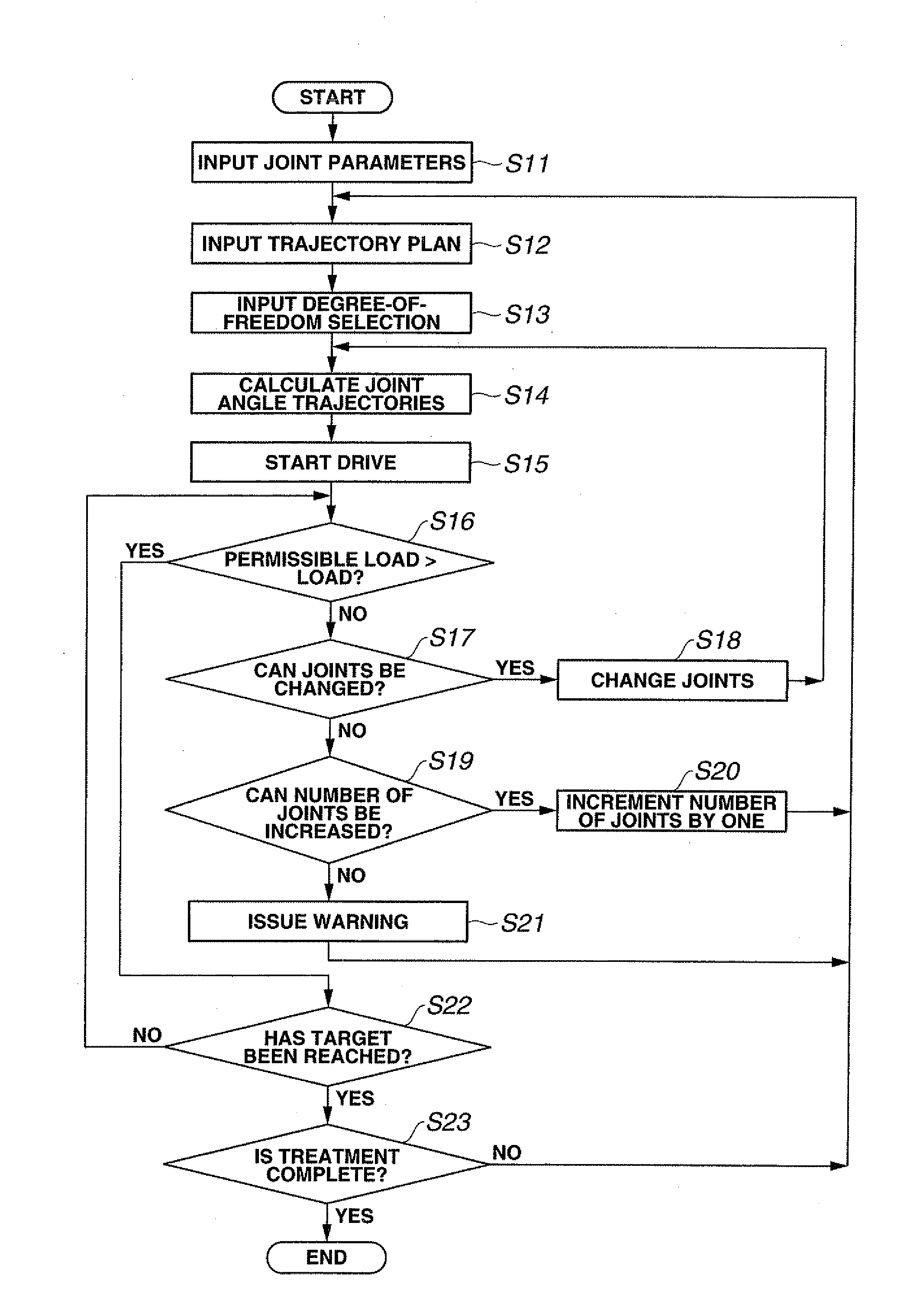
A medical device system includes a manipulator including a plurality of joints, a parameter storing portion for storing joint parameters, including a largest available force, of each joint of the plurality of joints, a trajectory inputting portion for inputting, as a trajectory plan, trajectories for moving a distal end of the manipulator from a current position and attitude to a target position and attitude, a trajectory setting portion for setting a joint angle trajectory for each joint providing a largest available force from among joint angle trajectories which allow movement to the target position and attitude with a minimum number of driven joints based on a largest available force parameter for the each joint stored in the parameter storing portion and the trajectory plan.

Description

CROSS REFERENCE TO RELATED APPLICATION[0001]This application claims benefit of Japanese Application No. 2007-282144 filed on Oct. 30, 2007; the contents of which are incorporated by this reference.BACKGROUND OF THE INVENTION[0002]1. Field of the Invention[0003]The present invention relates to a manipulator apparatus and a medical device system, and in particular to a manipulator apparatus having a plurality of joints driven efficiently in a manner dependent on a target treatment and to a medical device system which includes the manipulator apparatus.[0004]2. Description of the Related Art[0005]In recent years endoscopic surgery for performing various treatments inside a body cavity has become widespread. The endoscopic surgery is performed by opening an insertion hole in a body wall and inserting an endoscope and treatment instruments percutaneously into a body cavity through the insertion hole. This type of technique does not require a large dissection and is widely applied as a mi...

Claims


Application Information

Patent Timeline
IPC IPC(8): A61F2/02B25J13/08B25J9/06B25J19/02B25J17/02G06F19/00A61B1/00A61B17/00A61B17/28A61B17/32A61B19/00B25J9/10B25J13/00
CPCA61B19/2203A61B19/5212A61B2017/00314B25J9/16A61B2019/2238A61B2019/2242A61B2019/464A61B2019/2223A61B2090/064A61B34/71A61B90/361A61B34/30A61B34/37A61B2034/306B25J9/1633B25J9/1643
Inventor UMEMOTO, YOSHITAKATAKAHASHI, KAZUHIKONONAMI, TETSUO
Owner OLYMPUS CORP
Learn More