Unlock instant, AI-driven research and patent intelligence for your innovation.

Data processing method of decoding coded data and data processor for the same

Inactive Publication Date: 2009-04-30
RENESAS ELECTRONICS CORP
View PDF5 Cites 2 Cited by
  • Summary
  • Abstract
  • Description
  • Claims
  • Application Information

AI Technical Summary

Benefits of technology

[0023]With the technology according to the present invention, in decoding the data that was error correction coded, the error correction capability can be enhanced more.

Problems solved by technology

In the communication channel, there is a possibility that a noise leading to an error may mix with this data.
If errors are detected frequently, then many retransmissions will also occur and efficiency of the communication system will fall.
Especially, in mobile communication systems, since the intensity of a radio wave varies substantially due to influences of fading etc. and noise is easy to mix, this problem is salient.
However, when decoding, an error in other data for which this portion of the data was used cannot be corrected, and an improvement effect of the error correction capability is restricted.

Method used


Image

  • Data processing method of decoding coded data and data processor for the same
  • Data processing method of decoding coded data and data processor for the same
  • Data processing method of decoding coded data and data processor for the same

Examples


first exemplary embodiment

[0073]FIG. 9 shows a receiver set 100 according to a first exemplary embodiment of the present invention. This receiver set 100 receives data via a network, for example, a wireless communication network, and decodes received data. As an example, in this embodiment, the received data is the user data that was error detection coded and error correction coded and that was further modulated in the transmitting side. As the error correcting code, a convolutional code is used. Moreover, the receiver set 100 uses a technique of Viterbi decoding when decoding.

[0074]As shown in FIG. 9, the receiver set 100 is equipped with an antenna 110, a demodulator unit 112, a control data decoder unit 114, a CPU (Central Processing Unit) 116, and a user data decoder unit 120.

[0075]The antenna 110 receives data via a wireless communication network, and outputs the received data to the demodulator unit 112. The demodulator unit 112 demodulates the received data. If the demodulated data is the control data...

second exemplary embodiment

[0098]As a second exemplary embodiment of the present invention, FIG. 11 shows a user data decoder unit 220 to which the present invention can be applied instead of the user data decoder unit 120 in the receiver set 100 shown in FIG. 1. In FIG. 11, the same components as those in the user data decoder unit 120 shown in FIG. 10 are given the same reference numerals and their explanations are omitted.

[0099]In the user data decoder unit 220 shown in FIG. 11, a controller 230 is equipped with functions of the first substitution unit 152, the monitoring unit 154, the second substitution unit 164, and the monitoring unit 166, in addition to a function of the controller 130 of the user data decoder unit 120 shown in FIG. 10. Therefore, a Viterbi decoder 250 does not have components that bear these functions, comprising the ACS arithmetic unit 156, the internal memory 160, and the traceback unit 162.

[0100]The controller 230 calculates the address and size of the substitution object part in ...

third exemplary embodiment

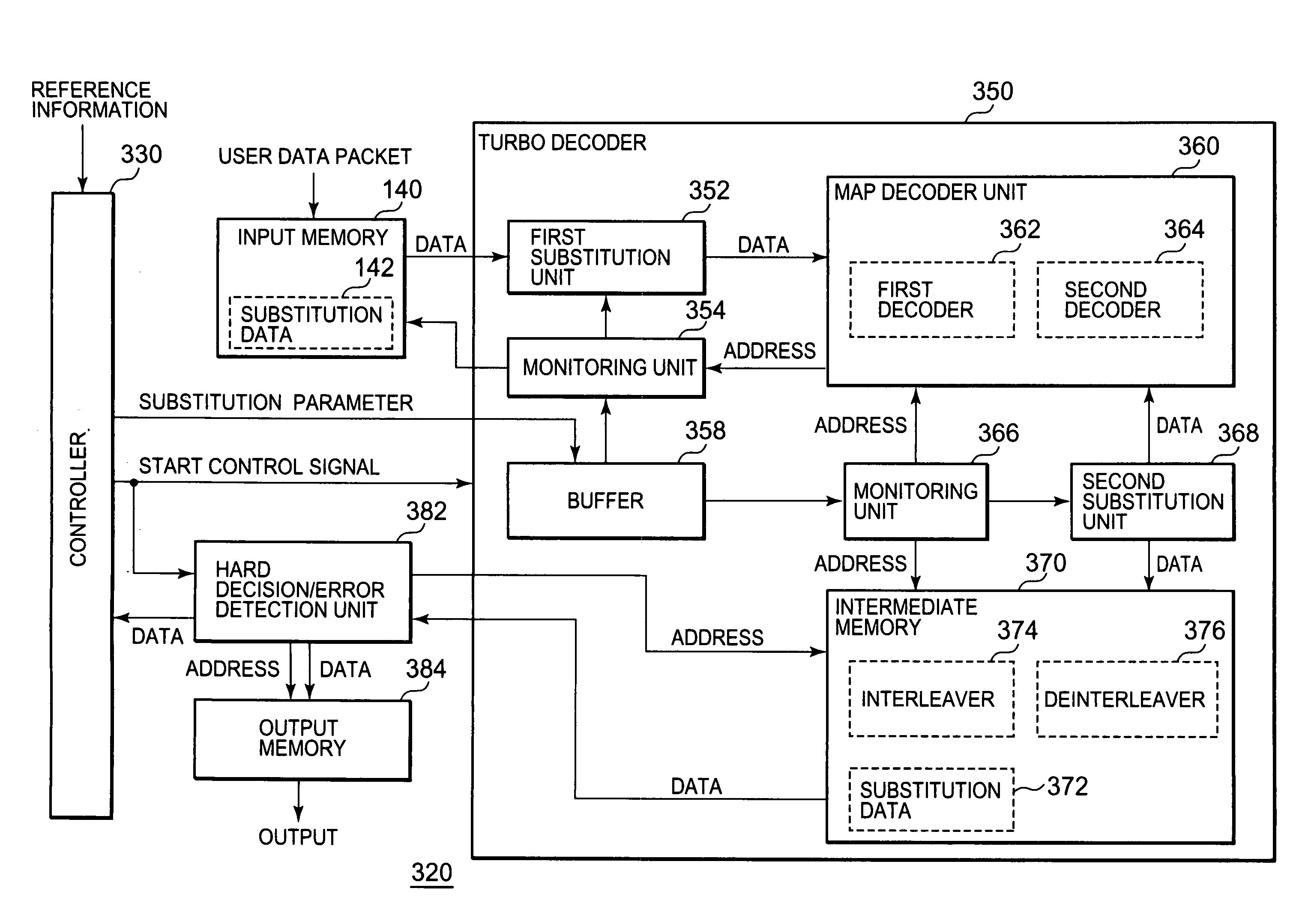
[0106]FIG. 13 shows a user data decoder device 320 according to a third exemplary embodiment of the present invention. This user data decoder device 320 is, when the receiver set 100 shown in FIG. 9 receives the turbo coded data, one to which the present invention is applied instead of the user data decoder unit 120 in the receiver set 100. In FIG. 13, components that are the same as those in the user data decoder unit 120 shown in FIG. 10 are given the same reference numerals and their explanations are omitted. In addition, as an example, modes of the coded data are three kinds, “Systematic,”“First Parity,” and “Second Parity” shown in FIG. 5.

[0107]The user data decoder device 320 is equipped with a controller 330, the input memory 140, a turbo decoder 350, a hard decision / error detection unit 382, and output memory 384.

[0108]The input memory 140 stores the coded user data packet, and also stores the substitution data 142. This substitution data 142 is a code specified by the stand...


PUM


Abstract

For the coded data that was transmitted via a communication channel, a known code portion thereof that is a code portion corresponding to known data is detected. When the known code portion is not detected from the coded data, the coded data will be decoded. When the known code portion is detected from the coded data, at least a part thereof will be replaced with normal data, and the decoding will be performed on the coded data after the substitution.

Description

BACKGROUND OF THE INVENTION[0001]1. Field of the Invention[0002]The present invention relates to data processing technology, and more specifically, to a technology of decoding coded data.[0003]2. Description of Related Art[0004]In the digital transmission system, in order to secure reliability of data transmitted and received, the error correcting code and the error detecting code are used. FIG. 16 is a schematic diagram that outlines a digital transmission system in which an error correcting code and an error detecting code are used.[0005]As shown in FIG. 16, the transmitting side performs error detection coding and error correction coding on the data that is intended to be transmitted to the opposite party (transmission data), subsequently modulates it to obtain the modulated coded data, and outputs it into a communication channel. In the communication channel, there is a possibility that a noise leading to an error may mix with this data.[0006]A receiving side demodulates the rec...

Claims


Application Information

Patent Timeline
IPC IPC(8): H03M13/05G06F11/08
CPCH03M13/2957H03M13/3994H04L1/0078H04L1/0054H03M13/41
Inventor ORIO, MASAOTAKANASHI, MITSUNORI
Owner RENESAS ELECTRONICS CORP
Features
  • R&D
  • Intellectual Property
  • Life Sciences
  • Materials
  • Tech Scout
  • Unparalleled Data Quality
  • Higher Quality Content
  • 60% Fewer Hallucinations
Learn More