
Infrared dryer

a dryer and infrared technology, applied in drying machines, lighting and heating apparatus, furniture, etc., can solve the problems of excessive heating, deterioration of heating ad drying performance, and large volume of design,

Inactive Publication Date: 2009-05-07
TENG SHI YU
View PDF7 Cites 13 Cited by
  • Summary
  • Abstract
  • Description
  • Claims
  • Application Information

AI Technical Summary

Benefits of technology

[0011]It is another object of the invention to provide an infrared dryer that prevents any aggregation of stock to be dried.
[0012]It is still another object of the invention to provide an infrared dryer that drives a cylinder to firmly rotate while has less need of replacing its transmittal device.
[0013]It is another object of the invention to provide an infrared dryer with easy maintenance of infrared light tubes.
[0014]It is another object of the invention to provide an infrared dryer that increases the temperature difference between the stock core and the stock surface to improve drying performance.
[0015]It is another object of the invention to provide an infrared dryer that prolongs the service life of the infrared light tube, increases mixing efficiency of the drying / dried / un-dried stock particles, and reduce the generation of powders.

Problems solved by technology

However, this design has huge volume and will need high production cost.
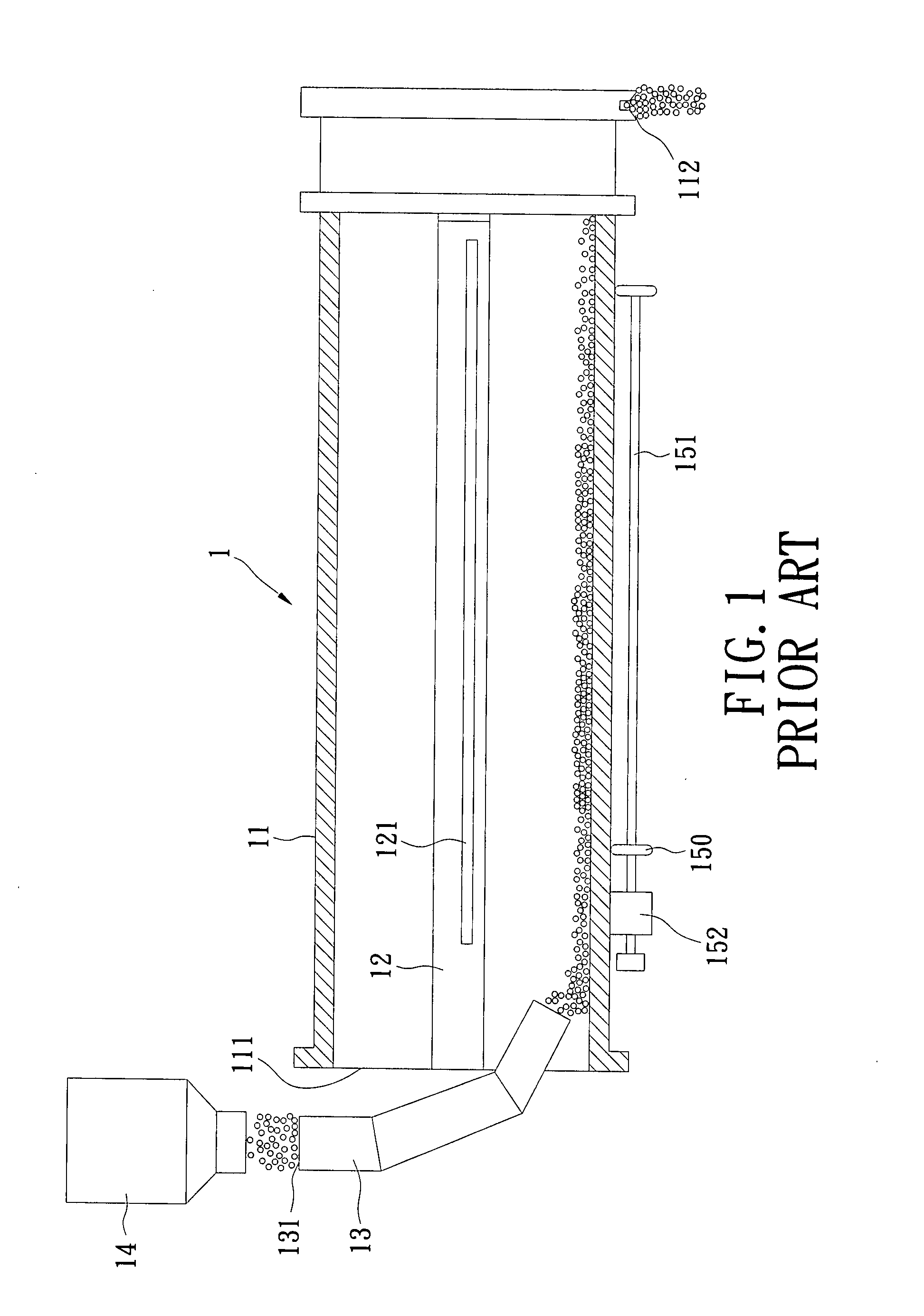
If the particles cannot be agitated thoroughly, some of them could be excessively heated and aggregated onto an inner wall of the cylinder 11.
As the aggregation become more and more serious, the heating ad drying performance deteriorates and therefore frequent maintenance need.
After used for a certain period of time, the rollers 150 at the bottom of the cylinder 11 suffer different levels of wearing and thus have different surface roughness and surface distortion which caused the cylinder to lose its balance during operation.

Method used


Image

  • Infrared dryer
  • Infrared dryer
  • Infrared dryer

Examples


Embodiment Construction

[0030]Wherever possible in the following description, like reference numerals will refer to like elements and parts unless otherwise illustrated.

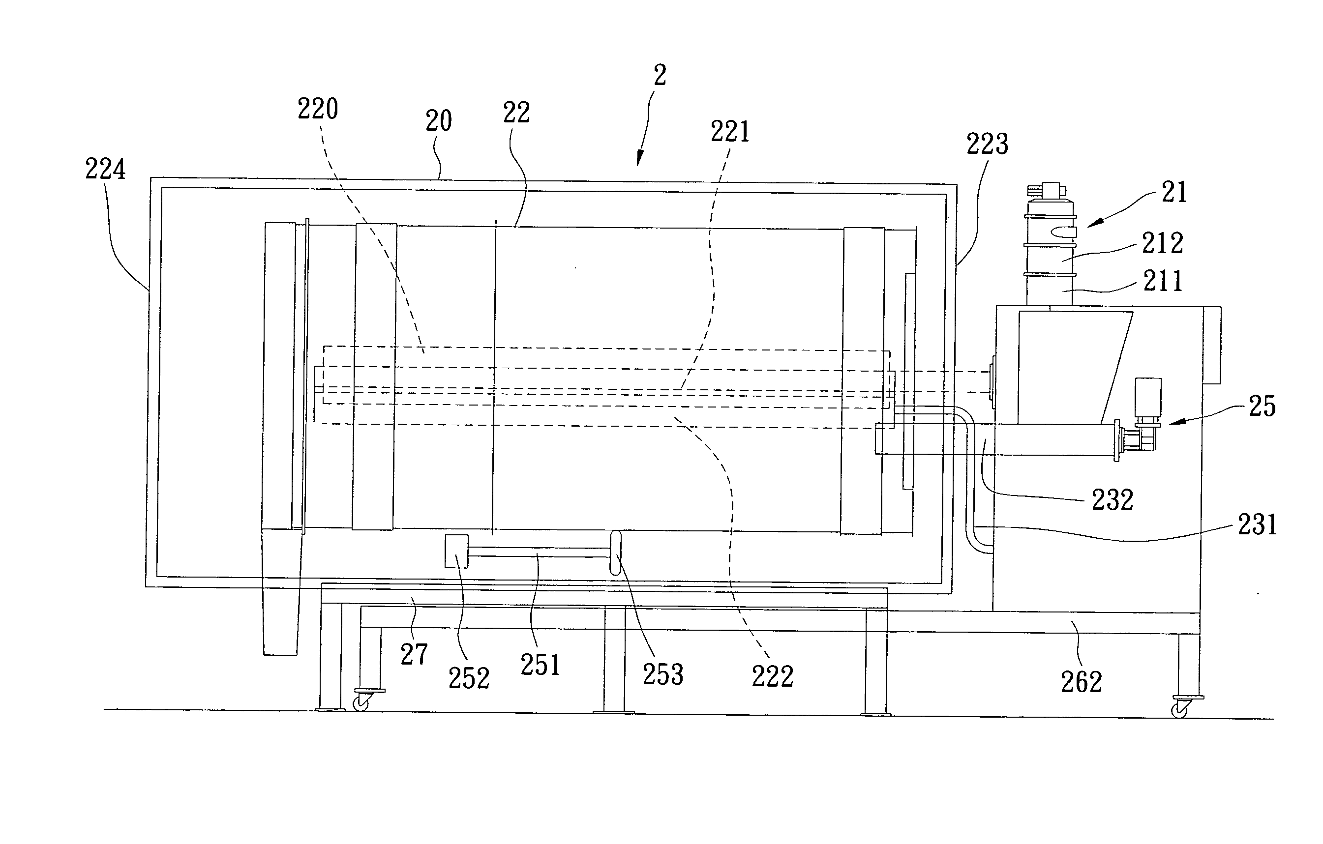
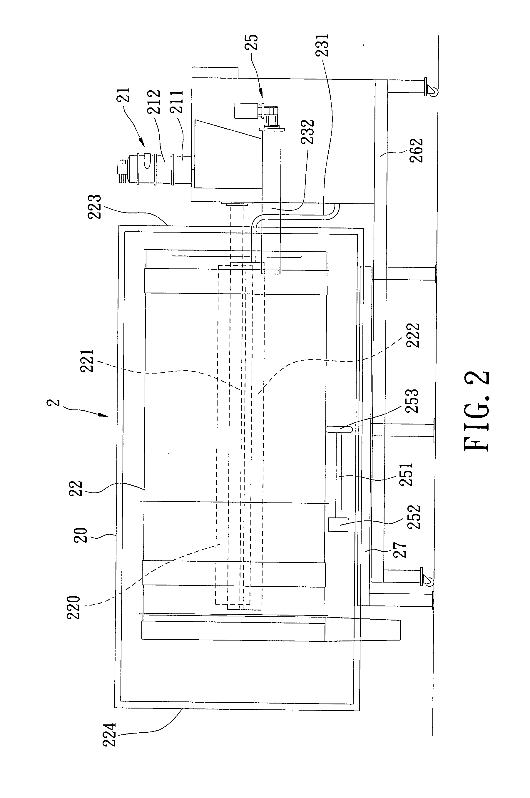
[0031]Referring to FIG. 2, an infrared dryer according to one embodiment of the invention includes a feeding device 21, a feeding controller 25, an infrared dryer body 2, a sliding assembly 26 and a holder 27.

[0032]The infrared dryer body 2 is preferably of cylindrical shape. At substantially central location of the infrared dryer body 2 are mounted an infrared light tube 221 and an infrared light lampshade 222 covering the whole infrared light tube 221. The infrared light tube 221 is fixed inside the infrared light lampshade 222 an end of which is secured to the feeding controller 25. The feeding device 21 has a stock container 212 and an entrance 211 under the stock container 212. The entrance 211 is connected to the feeding controller 25. The feeding controller 25 controls time period of operating the infrared light tube 221 and the infr...


PUM


Abstract

An infrared dryer with an infrared dryer body is disclosed. The infrared dryer body includes a cylinder; an infrared light tube, located at substantially central location of the infrared dryer body; an infrared light lampshade, located above the infrared light tube to cover substantially the whole infrared light tube; and at least one shield located above the lampshade inside the cylinder to cover the whole lampshade.

Description

BACKGROUND OF THE PRESENT INVENTION[0001]1. Field of the Present Invention[0002]The present invention generally relates to an infrared dryer, and particularly to an infrared dryer which provides mixing function as well.[0003]2. Description of the Related Art[0004]Infrared rays are able to convey energy to particles without the use of any media. The energy generates heat to cause molecules to vibrate so that the water inside particles is vaporized to become moistures. Air outside and around the particles is cooler than the moisture inside the particles, and a temperature difference is generated to drive the moisture to leave from the particles. The particles are thereby dried.[0005]The infrared drying is done by means of the temperature difference between the cooler air and the warmer moisture inside the particles. The temperature difference creates pressure gradient which is also a driving force to remove the moisture. Compared to drum blower and vacuum drier which take long to dry ...

Claims


Application Information

Patent Timeline
Patent Type & Authority Applications(United States)
IPC IPC(8): F26B3/34
CPCF26B11/0495
Inventor TENG, SHI-YUWANG, CHEN-YUAN
Owner TENG SHI YU
Learn More