Wheel Support Bearing Assembly Equiped with Sensor

a technology of bearings and sensors, applied in the direction of instruments, force/torque/work measurement apparatuses, transportation and packaging, etc., can solve problems such as strain in the sensor unit, and achieve the effect of compact installation and simplified labor

Inactive Publication Date: 2009-05-07
NTN CORP
View PDF15 Cites 30 Cited by
  • Summary
  • Abstract
  • Description
  • Claims
  • Application Information

AI Technical Summary

Benefits of technology

[0008]In view of the above, an object of the present invention is to provide a sensor incorporated wheel support bearing assembly, in which the sensor for detecting the load can be snugly and neatly installed in an automotive vehicle, the load acting on the vehicle wheel can be detected with high sensitivity and the cost of manufacture can be reduced during a mass production.

Problems solved by technology

In the event that a load acts on the rotatable member as the automotive vehicle starts traveling, the stationary member undergoes deformation through the rolling elements and such deformation brings about a strain in the sensor unit.

Method used


Image

  • Wheel Support Bearing Assembly Equiped with Sensor
  • Wheel Support Bearing Assembly Equiped with Sensor
  • Wheel Support Bearing Assembly Equiped with Sensor

Examples


second embodiment

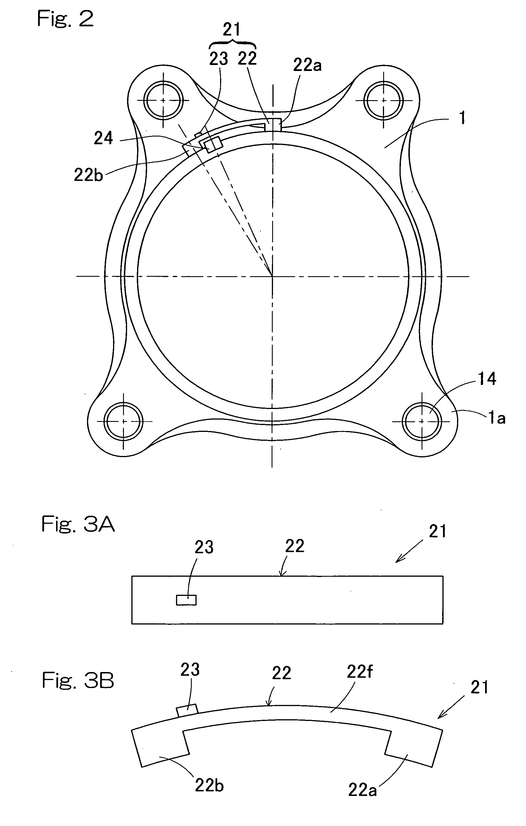
[0084]FIGS. 6 and 7 illustrate a second preferred embodiment of the present invention. The wheel support bearing assembly according to this second embodiment is of a type in which fixing of the sensor mounting member 22 to the outer member 1 is carried out by the use of bolts. As best shown in FIG. 7, the entire shape of this sensor mounting member 22 is the same as that of the sensor mounting member 22 shown in FIG. 3 and a bolt insertion hole 40 is formed in each of the first and second contact fixing portions 22a and 22b. The outer member 1 is formed with a bolt threading hole 41 having an inner peripheral surface threaded and defined therein at a location corresponding to each of the bolt insertion holes 40. As shown in FIG. 6, the sensor unit 21 is fixed on the outer member 1 with the bolts 42 passed from an outer peripheral side through the respective bolt insertion holes 40 and with male threaded portions 42a of those bolts 42 subsequently threaded in the associated bolt thre...

first embodiment

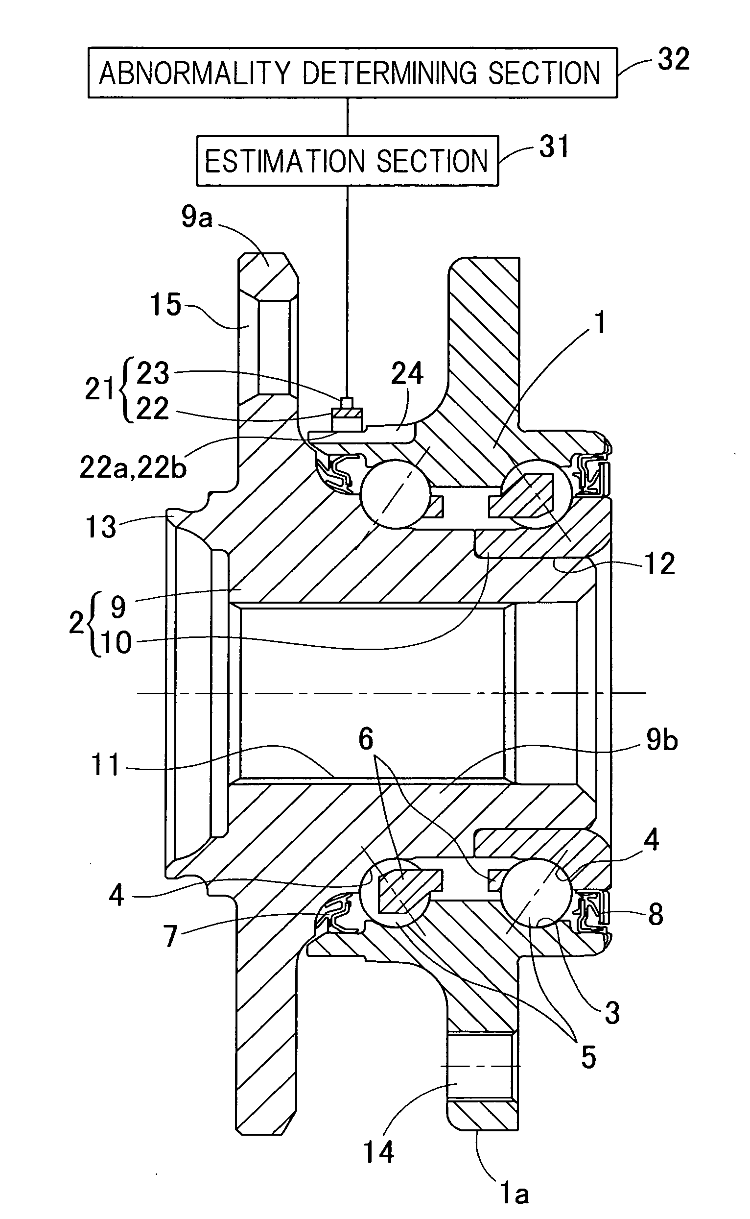
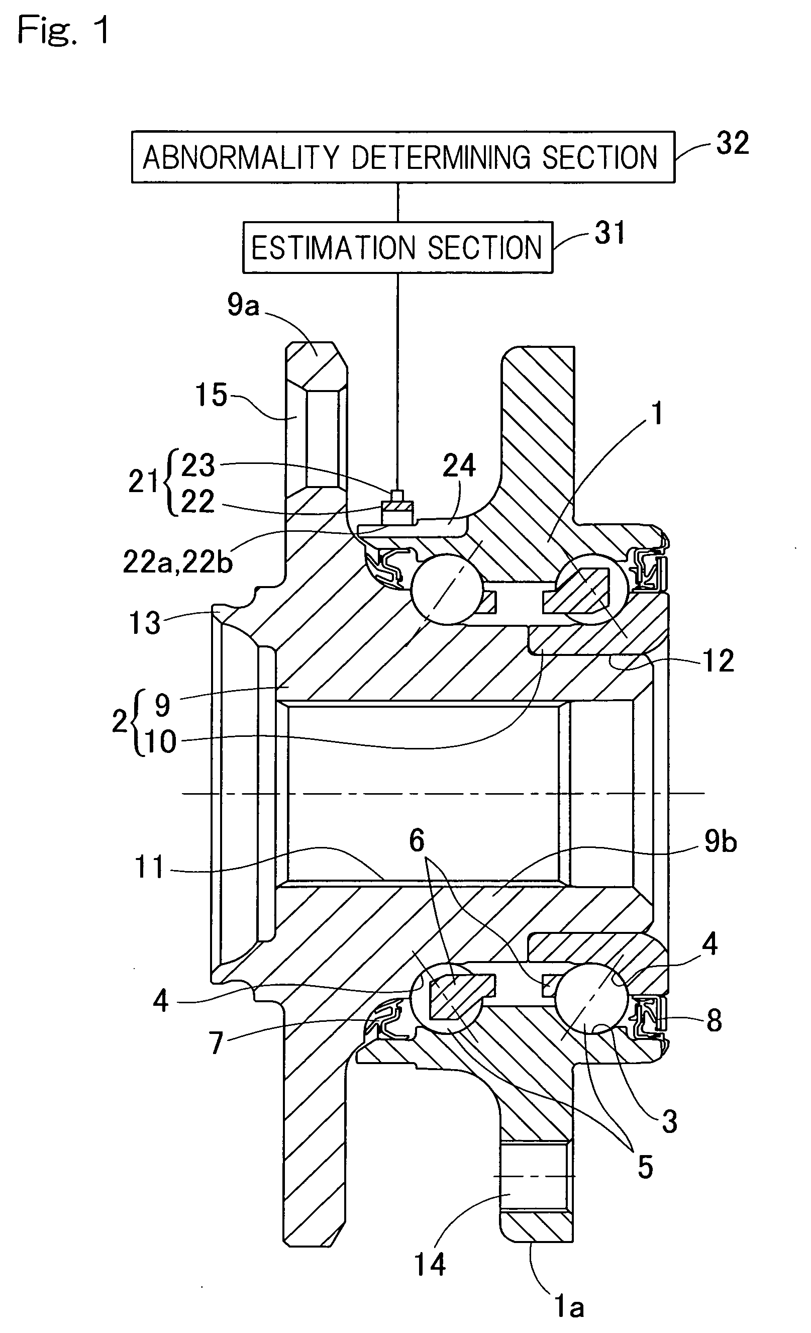
[0115]As shown in FIG. 14, as section for processing an output from each of the strain sensors 23, an estimation section 31 and an abnormality determining section 32 are employed in a manner similar to the first embodiment particularly shown in FIG. 1. Those sections 31 and 32 may be those provided in an electronic circuit device (not shown) such as, for example, a circuit substrate fitted to the outer member 1 or the like of the wheel support bearing assembly or those provided in an electronic control unit (ECU) of an automotive vehicle.

[0116]The operation of the wheel support bearing assembly of the structure hereinabove described will now be described. When a load is applied to the hub unit 9, the outer member 1 is deformed through the rolling elements 5 and such deformation is transmitted to the sensor mounting member 22 that is fitted to the outer member 1, resulting in deformation of the sensor mounting member 22. The strain of this sensor mounting member 22 is measured by the...


PUM


Abstract

In a wheel support bearing assembly including a plurality of rolling elements (5) interposed between an outer member (1) and an inner member (2), a sensor unit (21) is fitted to one of the outer member and the inner member, which serves as a stationary member. The sensor unit includes a sensor mounting member (22) and a strain sensor (23) fitted to the sensor mounting member. The sensor mounting member has a plurality of contact fixing portions (22a, 22b) that are fixed to at least two locations spaced a distant from each other in a direction circumferentially of the outer member. A cutout (24) is provided in the outer member at respective positions corresponding to the neighboring contact fixing portions of the sensor mounting member, so as to extend in an axial direction. The strain sensor is arranged intermediate between the neighboring contact fixing portions.

Description

BACKGROUND OF THE INVENTION[0001]The present invention relates to a sensor incorporated wheel support bearing assembly having a load sensor built therein for detecting a load imposed on a bearing unit of a vehicle wheel.DESCRIPTION OF THE PRIOR ART[0002]For safety travel of an automotive vehicle, the wheel support bearing assembly has hitherto been well known in the art, which is equipped with a sensor for detecting the rotational speed of one of automotive wheels. While the automobile traveling safety precaution is generally taken by detecting the rotational speed of a vehicle wheel of various parts, it is not sufficient with only the rotational speed of the wheel and, therefore, it is desired to achieve a control for safety purpose with the use of other sensor signals.[0003]In view of the above, it may be contemplated to achieve the vehicle attitude control based on a load acting on each of the wheels during travel of an automotive vehicle. By way of example, a large load acts on ...

Claims


Application Information

Patent Timeline
Patent Type & Authority Applications(United States)
IPC IPC(8): G01M17/013
CPCB60B27/00B60B27/0005B60B27/0068F16C19/522F16C19/186G01L5/0019B60B27/0094F16C41/00F16C2326/02
Inventor OZAKI, TAKAYOSHIISHIKAWA, TOMOMINISHIKAWA, KENTAROU
Owner NTN CORP
Why Eureka
Try Eureka