Beverage system

a technology for drinking water and water dispensers, applied in the field of drinking water systems, can solve the problems of wasting space, saving costs, and particularly serious problems, and achieve the effect of reducing space requirements and costs, and particularly simple cleaning of water dispensers

a technology for drinking water and water dispensers, applied in the field of drinking water systems, can solve the problems of wasting space, saving costs, and particularly serious problems, and achieve the effect of reducing space requirements and costs, and particularly simple cleaning of water dispensers

US20090114099A1Active Publication Date: 2009-05-07WMF GRP

Image

  • Beverage system
  • Beverage system
  • Beverage system

Examples


Embodiment Construction

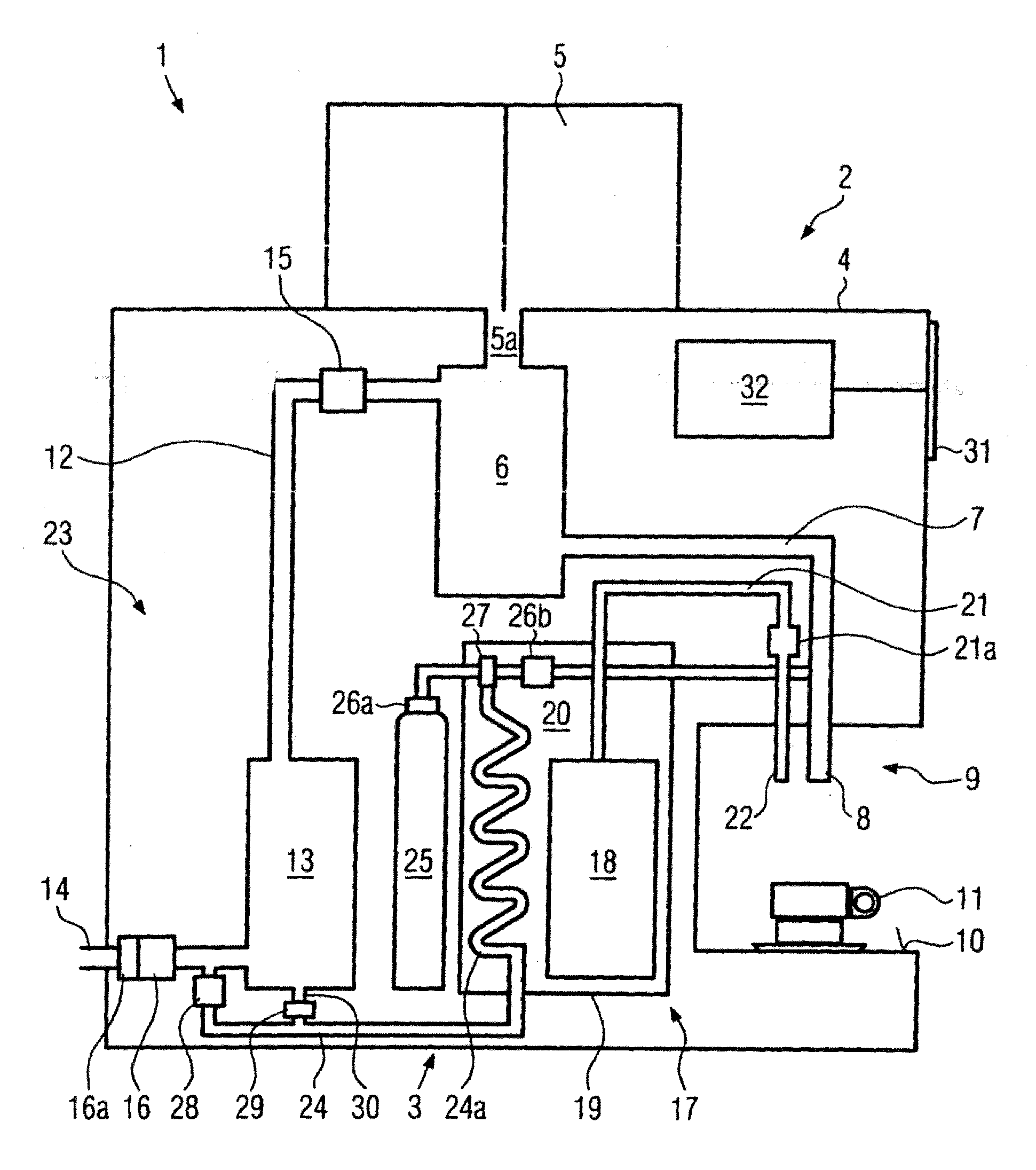
[0015]FIG. 1 shows a strongly schematic representation of essential components of a beverage system 1 according to the present disclosure. The beverage system 1 comprises a coffee machine 2 and a water dispenser 3, which, in the embodiment shown, are accommodated in a common housing 4. It is, however, also possible to accommodate the coffee machine 2 and the water dispenser 3 in separate housings and to interconnect these housings through conduits in a manner which will be described hereinbelow.

[0016]The coffee machine 2 comprises the normal components which are necessary or desirable for automatic coffee makers and which guarantee that the coffee machine 2 prepares and dispenses hot beverages (brewed beverages), e.g. especially coffee, in an automatic or predominantly automatic manner.

[0017]In order simplify the representation, the figure only shows a container 35, which contains the raw material for brewed beverages, such as two sorts of coffee beans or coffee grounds for filter c...


PUM


Abstract

The present invention describes a beverage system (1) comprising a coffee machine (2) for preparing and dispensing hot beverages, and a water dispenser (3) for processing and dispensing drinking water; this system is inexpensive and it requires little space. To this end, it is suggested that wherein the coffee machine (2) and the water dispenser (3) should be connected to one another in such a way that at least one functional component of the coffee machine (2) or of the water dispenser (3) can be utilized both for the coffee machine (2) and for the water dispenser (3).

Description

CROSS-REFERENCE TO RELATED APPLICATION[0001]The present application claims the benefit of priority of International Patent Application No. PCT / EP2006 / 007205, filed on Jul. 21, 2006, which application claims priority of EP Patent Application No. 050116579.4, filed Jul. 29, 2005. The entire text of the priority application is incorporated herein by reference in its entirety.FIELD OF DISCLOSURE[0002]The present disclosure relates to a beverage system comprising a coffee machine.BACKGROUND[0003]The customers' liking tends, at present, more and more towards light, nonalcoholic beverages and in particular towards water. A great variety of water dispensers is known, which are able to process tap water such that it is suitable for being served as table water, i.e. which are especially able to cool tap water or to add a gas, preferably carbon dioxide or oxygen, thereto. Such water dispensers are known e.g. from DE-U-298 16 612, DE-B-1 99 60 149, WO-A-02 / 02455 or WO-A-93 / 10035. However, also ...

Claims


Application Information

Patent Timeline
07 May 2009
Publication
US20090114099A1
IPC
A47J31/44; B67D5/06; B67D5/63; B67D7/06; B67D7/82
CPC
A47J31/60; A47J31/007
Inventors
GOTLENBOTH, FRANK