
Methods for fuel-efficient transportation of cargo by aircraft

a technology for aircraft and cargo, applied in the field of cargo aircraft, can solve the problems of poor aerodynamic and fuel efficiency, high cost, and low fuel efficiency of jet engines, and achieve the effects of less concern for speed, high fuel efficiency and low speed

Inactive Publication Date: 2009-05-07
HELOU JR ELIE
View PDF20 Cites 31 Cited by
  • Summary
  • Abstract
  • Description
  • Claims
  • Application Information

AI Technical Summary

Benefits of technology

[0006]Because the cargo drone does not require a pilot or crew on board, flight times are no longer constrained by considerations of avoiding pilot and crew fatigue. Thus, a cargo drone can fly at more fuel-efficient low speeds for long distances and at lower altitudes. Because speed is no longer a concern, the cargo drone may utilize a more fuel efficient engine, such as a piston engine or a turboprop, and fly at altitudes significantly lower than that required of jet engine airlines. The use of a piston or turboprop engine, in turn, allows for the possibility of utilizing renewable fuel, such as biodiesel, which is not suitable for use with jet engines. The cargo drone may therefore be designed for highly efficient flight profiles without needing to accommodate a crew and passengers.
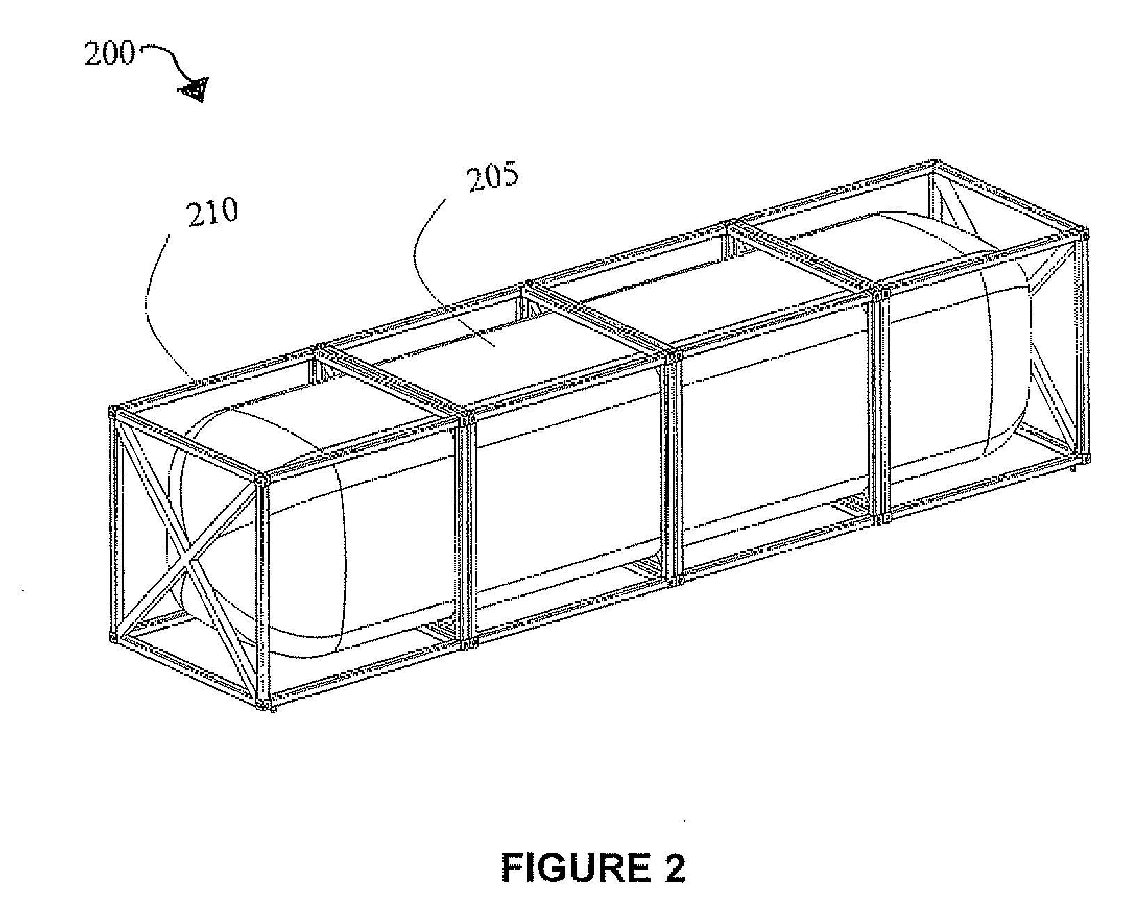
[0008]The cargo drone suitable for use in connection with the disclosed methods are constructed with the minimal structural requirement, including a forward fuselage, an empennage, a beam structure connecting the forward fuselage to the empennage, and wings attached to the beam structure. Cargo drones suitable for use in connection with the methods are also disclosed in commonly-owned U.S. Pat. No. 7,261,257, which is hereby incorporated by reference as if fully set forth herein. The beam structure is designed to be as light as possible and the cargo containers are designed to provide the added strength to the beam structure to sustain the various forces which are exerted upon the aircraft in flight. Additional savings in weight are provided by the methods disclosed herein.
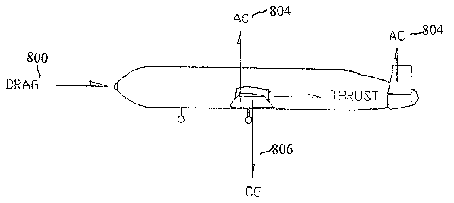
[0010]The filled container is then loaded onto a location on the aircraft beam relative to the aircraft's CG based on the weight of the filled container to stay within the acceptable CG range for the aircraft. The filled containers having the greater weight are positioned on the beam at or adjacent to the aircraft's CG and the filled containers having lower weight are positioned farther from the aircraft's CG. Once the aircraft is fully loaded, the filled containers provide strength and rigidity to the aircraft beam to sustain the bending and torsional loads in flight when it is loaded onto the aircraft beam.

Problems solved by technology

Since airplanes are most commonly used for transporting passengers, these parameters are optimized to provide safe, high-speed travel, at the cost of being expensive and providing poorer aerodynamic and fuel efficiency.
Jet engines, however, are not as fuel efficient as piston engines or turboprops.
Because aircraft of a size capable of carrying substantial cargo have typically been designed first as passenger aircraft, air cargo systems remain both expensive and inconvenient.
Adding weight to an aircraft negatively impacts the fuel economy.
Unfortunately, it is often difficult to accurately determine the placement of cargo containers, as they typically come in a wide variety of shapes, sizes and weight.
The inability of aircraft to participate in intermodal container cargo systems has been disadvantageous to international commerce.
The use of a piston or turboprop engine, in turn, allows for the possibility of utilizing renewable fuel, such as biodiesel, which is not suitable for use with jet engines.
However, this method of flying relies on the existence of a pilot in the aircraft and thus has not been used for drone aircrafts used for transporting cargo.

Method used


Image

  • Methods for fuel-efficient transportation of cargo by aircraft
  • Methods for fuel-efficient transportation of cargo by aircraft
  • Methods for fuel-efficient transportation of cargo by aircraft

Examples


Embodiment Construction

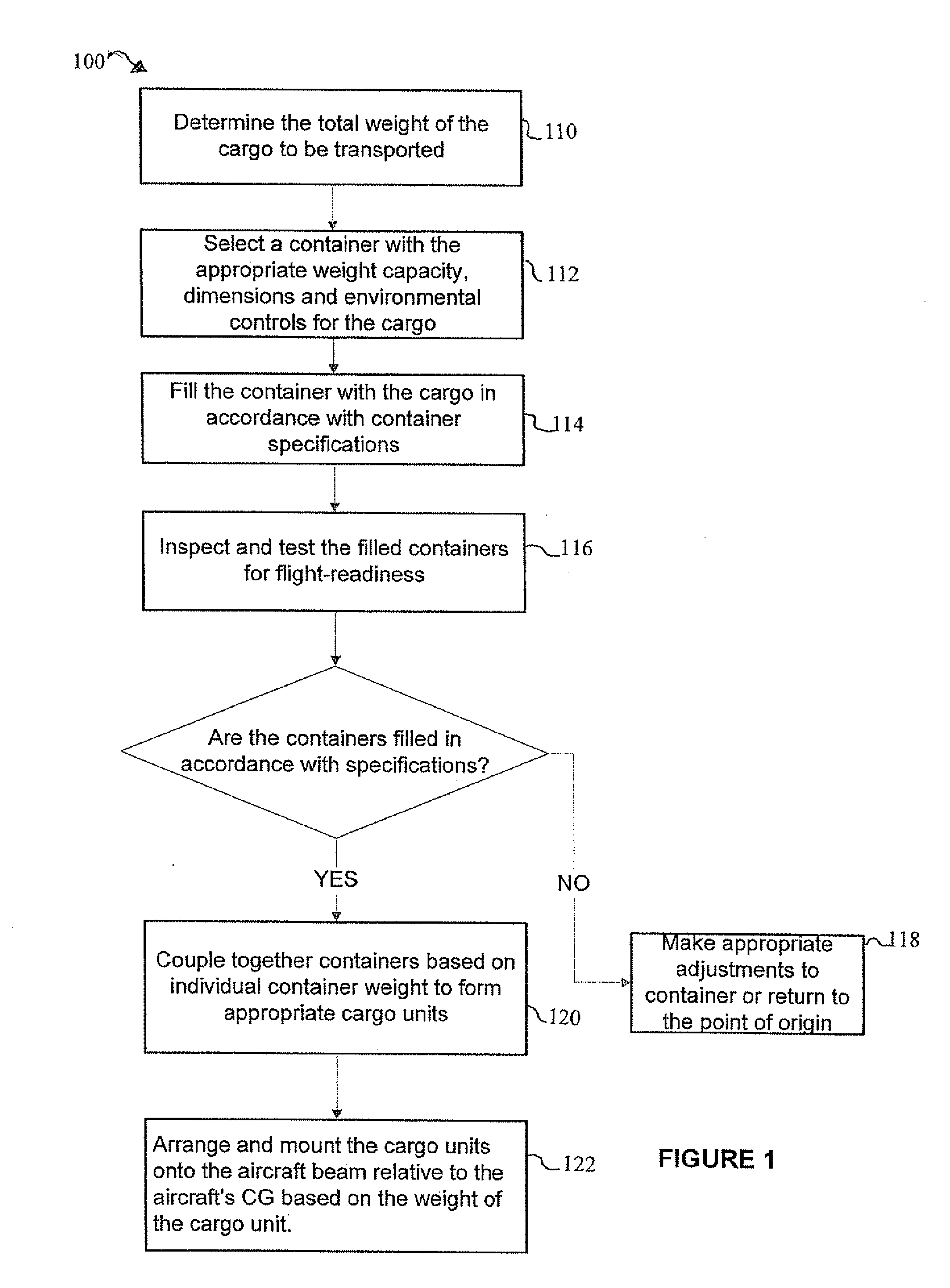
[0038]FIG. 1 is a flow diagram showing exemplary steps of a method 100 for transporting cargo to a desired location via an aircraft. As shown in step 110, the weight of cargo that is capable of being transported in a single container is determined. Since containers are available in a number of different standard sizes, the weight of the cargo to be transported will depend on the size of the desired container that will be used to transport it. Intermodal containers, for example, are available in a number of standard lengths, such as 20, 40, 45, 48, and 53 ft, and container capacity is typically measured in twenty-foot equivalent units. Because containers are available in a wide range of dimensions, there is flexibility with respect to whether and how cargo may be apportioned out among any number of containers.

[0039]Once the total weight of the cargo is determined, a container having the appropriate maximum weight capacity and environmental controls is selected 112. Since the containe...


PUM


Abstract

A fuel-efficient method for transporting cargo to a desired location via an aircraft. The method comprises determining the weight of the cargo capable of being transported in a single container, selecting a container having a sufficient weight capacity to support the cargo based on the determined weight of the cargo, and filling the selected container with the cargo. The filled container is loaded onto a location on the aircraft beam relative to the aircraft's CG based on the weight of the filled container to stay within the acceptable CG range for the aircraft. The filled containers having the greater weight are positioned on the beam at or adjacent to the aircraft's CG and the filled containers having lower weight are positioned farther from the aircraft's CG. The containers provide strength and rigidity to the beam to sustain the bending and torsional loads in flight.

Description

FIELD OF THE INVENTION[0001]The field of the present invention is cargo aircraft for transporting modular containers.BACKGROUND OF THE INVENTION[0002]Throughout aviation history, there has been a drive to make air transportation faster, more efficient and more cost effective. The basic parameters relevant to this objective include aerodynamics, engine efficiency and structural weight. Since airplanes are most commonly used for transporting passengers, these parameters are optimized to provide safe, high-speed travel, at the cost of being expensive and providing poorer aerodynamic and fuel efficiency. For example, passenger airlines use jet engines which provide much higher thrust than propellers and are naturally efficient at higher altitudes, being able to operate above 40,000 feet. Jet engines, however, are not as fuel efficient as piston engines or turboprops. Because aircraft of a size capable of carrying substantial cargo have typically been designed first as passenger aircraft...

Claims


Application Information

Patent Timeline
Patent Type & Authority Applications(United States)
IPC IPC(8): B64D9/00
CPCB64C1/061Y02T50/56B64C1/10B64C1/22B64C17/08B64C39/02B64C39/024B64C2201/128B64D9/00B64D13/02B64D13/06B64D2013/0629Y02T50/44Y02T50/46B64C1/065B64C2211/00Y02T50/40Y02T50/50B64U2101/60B64U30/10B64U10/25
Inventor HELOU, JR., ELIE
Owner HELOU JR ELIE
Learn More