
Inductive rotational speed sensors

a technology of rotational speed and sensors, applied in the field of sensors, can solve the problems of not being often used to measure the speed of a target, not being sensitive to noise, expensive, bulky, heavy, etc., and achieve the effects of increasing sensing precision, reducing speed, and increasing accuracy

Active Publication Date: 2016-03-15
SIMMONDS PRECISION PRODS
View PDF30 Cites 1 Cited by
  • Summary
  • Abstract
  • Description
  • Claims
  • Application Information

AI Technical Summary

Benefits of technology

The patent describes a way to improve the precision of detecting rotational speed by using non-axisymmetric resonance and receiver coils. By adding more windings or loops to the receiver coil and increasing the number of poles, the sensing precision can be improved even at lower rotational speeds. This results in a stronger and more reliable receive signal.

Problems solved by technology

This type of technology has been widely used for position sensing, but has not been often used to measure speed of a target.
These systems have many disadvantages, including being expensive, bulky, heavy, or sensitive to noise introduced in harsh operating environments such as those having mechanical vibrations and variable temperatures.
These systems are also subject to other sources of error including noise and signal interference associated with mounting analog signals around other sources of electromagnetic interference.

Method used


Image

  • Inductive rotational speed sensors
  • Inductive rotational speed sensors
  • Inductive rotational speed sensors

Examples


Embodiment Construction

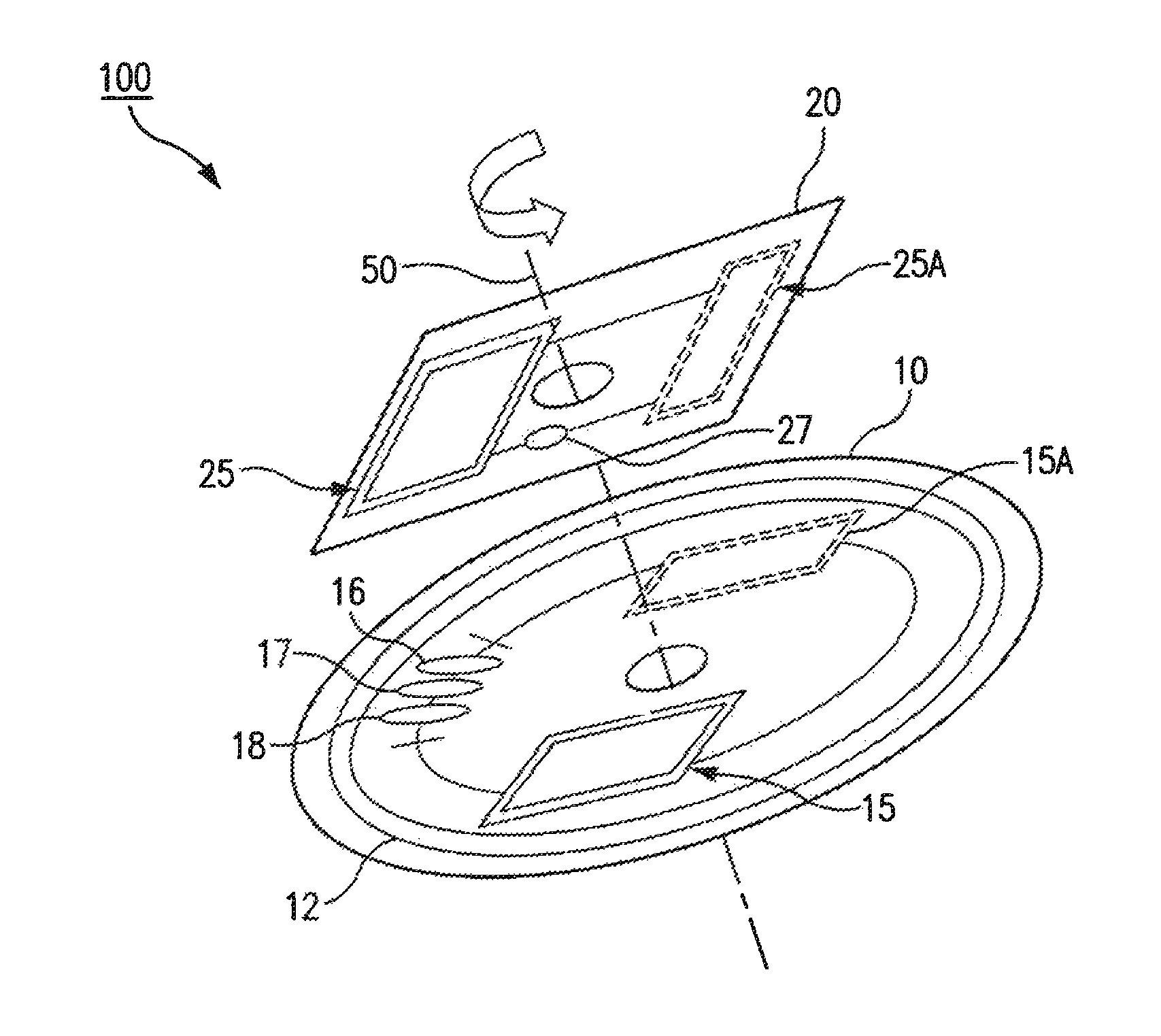
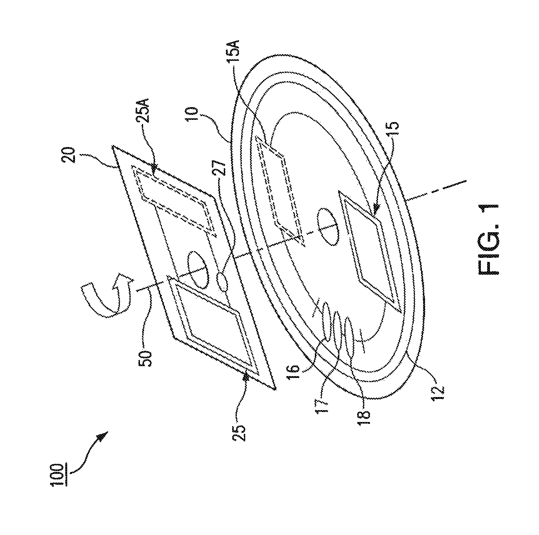
[0017]Reference will now be made to the drawings wherein like reference numerals identify similar structural features or aspects of the subject disclosure. For purposes of explanation and illustration, and not limitation, a partial view of an exemplary embodiment of the sensor assembly in accordance with the disclosure is shown in FIG. 1 and is designated generally by reference character 100. The systems and methods described herein can be used to provide a contactless rotational speed sensor using induction coupling and sensing.

[0018]Induction based rotational speed sensing in accordance with the disclosure can use electromagnetic coils made out of copper traces on a Printed Circuit Board (PCB). This sensor includes two adjacent PCBs separated by a nominally designed distance. The first PCB holds a high frequency electromagnetic field generator coil called the excitation or transmitter coil in addition to the sensing winding, also referred to as the receiver coil. The second PCB ho...


PUM


Abstract

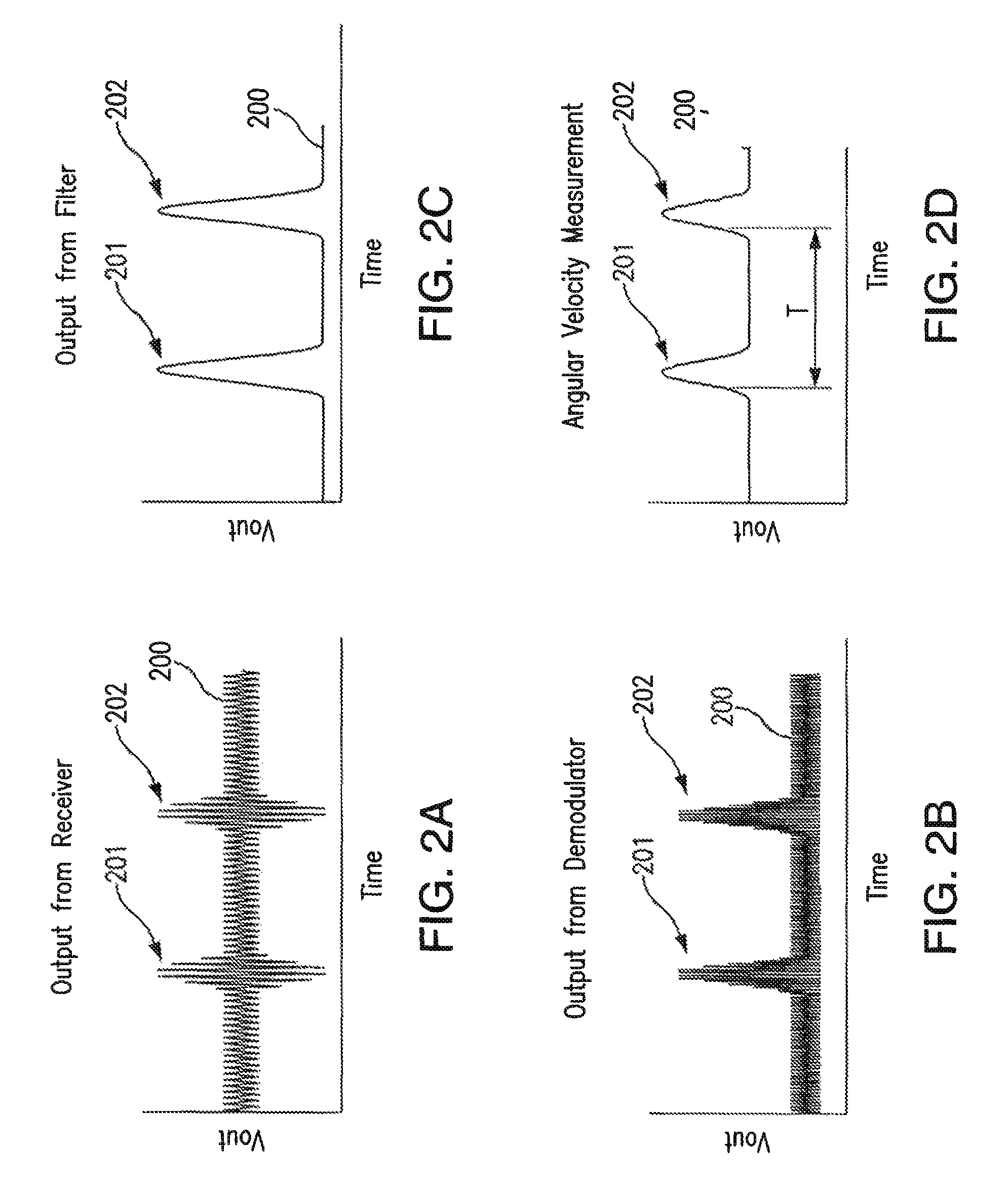
An inductive rotational speed sensor assembly includes a first PCB with a transmitter coil configured to convert an alternating electrical input into an alternating magnetic field. A second PCB is operatively connected to the first PCB for relative rotation and includes a resonance coil configured to couple to the alternating magnetic field of the first PCB to output a modulating position signal. The first PCB includes a receiver coil configured to receive the first and the modulating position signal and to output a signal indicative of rotational speed of the second PCB relative to the first PCB.

Description

CROSS-REFERENCE TO RELATED APPLICATIONS[0001]This application claims priority to U.S. Provisional Patent Application No. 61 / 912,709 filed Dec. 6, 2013, which is incorporated by reference herein in its entirety.BACKGROUND OF THE INVENTION[0002]1. Field of the Invention[0003]The present disclosure relates to sensors, and more particularly to inductive contactless sensors for measuring rotational speed.[0004]2. Description of Related Art[0005]Induction-based sensor technology uses sensing coils that are made of copper traces printed on electronic printed circuit board. This type of sensor is capable of measuring the relative position between a sensing printed circuit and a position target without being in physical contact with it. This technology is outlined for various applications in U.S. Pat. Nos. 6,534,970 and 8,129,985, each of which is incorporated by reference in its entirety. This type of technology has been widely used for position sensing, but has not been often used to measu...

Claims


Application Information

Patent Timeline
Patent Type & Authority Patents(United States)
IPC IPC(8): G01P3/48G01P3/488G01D5/20
CPCG01P3/48G01D5/204G01P3/488
Inventor HUYNH, CUONG T.ESSAWY, MAGDI A.
Owner SIMMONDS PRECISION PRODS
Learn More