
Method and system for control of at least a speed regulator

a technology of speed regulator and control system, which is applied in the direction of electric controller, electric control, instruments, etc., can solve the problems of optimum control of speed adjustment and fuel consumption, the risk of torque upramping and downramping being slow, and the subsequent potential for also optimising its fuel consumption, so as to achieve the effect of reducing torque inertia, improving efficiency and fuel efficiency

Inactive Publication Date: 2015-04-23
SCANIA CV AB
View PDF3 Cites 3 Cited by
  • Summary
  • Abstract
  • Description
  • Claims
  • Application Information

AI Technical Summary

Benefits of technology

The present invention allows for rapid changes in the engine system's torque, which can improve fuel efficiency in cruise control and speed regulation. By reducing the inertia of the engine system, the algorithm does not remember previous torque values, resulting in a more accurate speed curve. Additionally, the invention can control losses in the power train, such as by lowering exhaust backpressure or optimizing gearbox engagement. These measures can lead to increased efficiency and reduced fuel consumption.

Problems solved by technology

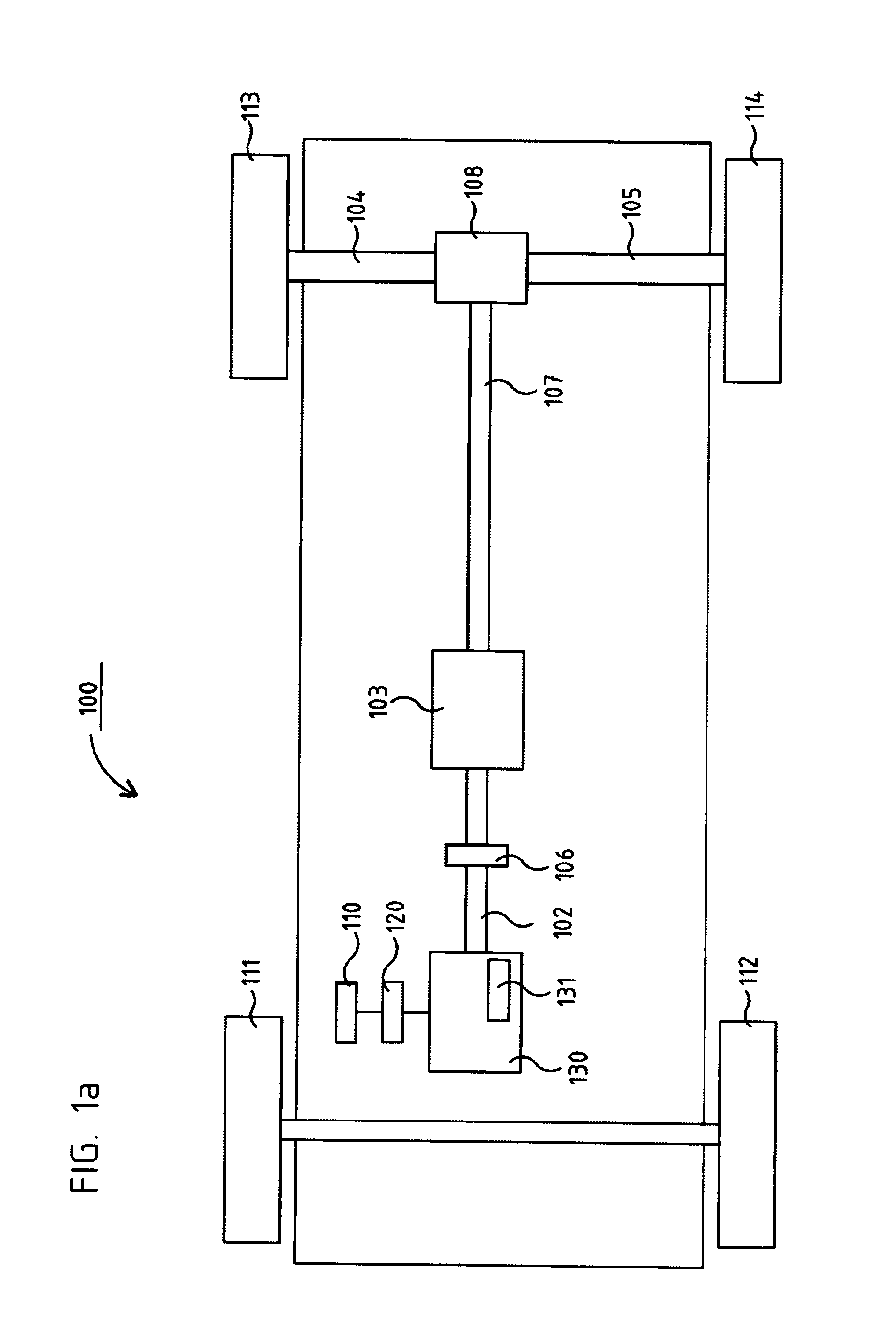
If the speed regulator 120 has for a lengthy period had in its algorithm a relatively large regulating error e, it is, depending on the function of the speed regulator's regulating algorithm, not possible to make the rapid changes in the torque M which are required to be able to follow an optimum curve for the vehicle's actual speed vact and thereby be able to optimise the vehicle's speed profile, with consequent potential for also optimising its fuel consumption.
There is therefore risk of torque uprampings and downrampings being slow, e.g. at large steps in the set-value vdes.
This slowness may cause problems as regards optimum control of speed adjustment and fuel consumption.
Particularly when there are relatively large changes in the vehicle's actual speed vact, e.g. when travelling uphill or downhill, this regulating error e will be relatively large for relatively long periods of time, with consequent build-up of inertia of the torque M.
As the reference speed vref here serves as the target speed vdes in the regulating algorithm, these adjustments of the reference speed vref often cause the regulating error e in the regulating algorithm, thereby building up the inertia of the torque M.

Method used


Image

  • Method and system for control of at least a speed regulator
  • Method and system for control of at least a speed regulator
  • Method and system for control of at least a speed regulator

Examples


Embodiment Construction

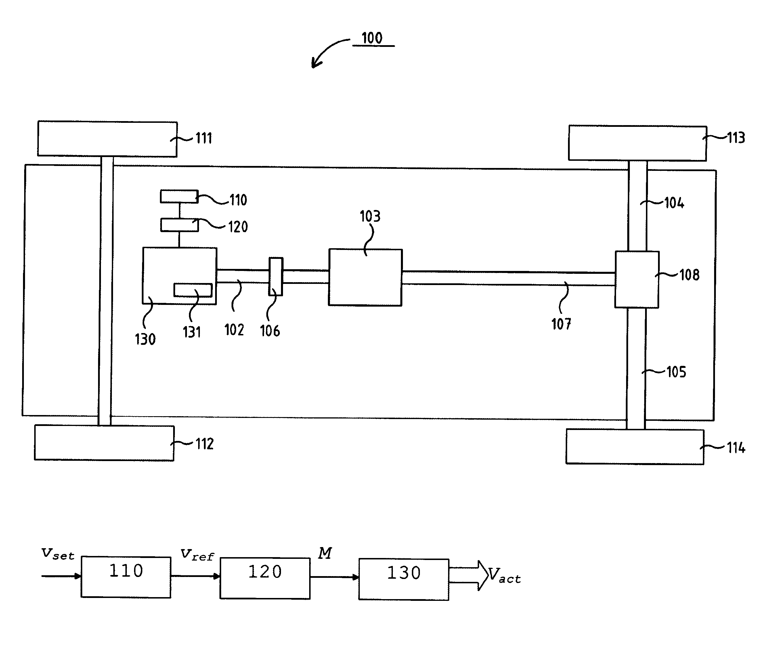
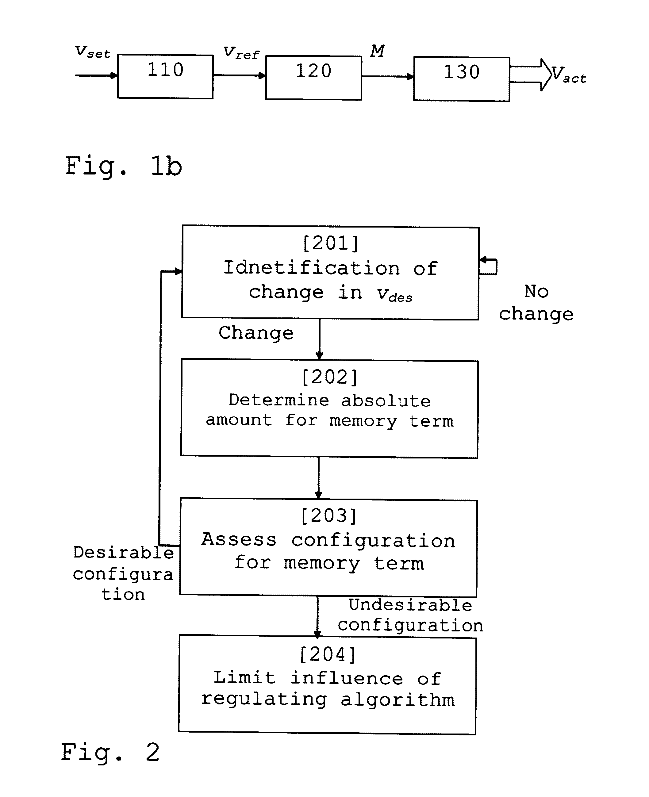
[0053]FIG. 2 is a schematic flowchart for the method according to an aspect of the present invention.

[0054]The method begins with a first step [201] in which a change in the target speed vdes is identified. As a second step [202] of the method, which is performed if a change in the target speed vdes is identified at the first step [201], an absolute amount is determined for a memory term of the regulating algorithm used by the regulating system. This memory term is related to a history of how the speed regulator previously regulated the engine system. If PID regulation is used, the magnitude of the I term ∫0te(τ)dτ d is determined by determining its absolute amount |∫0te(τ)dτ|.

[0055]The third step [203] of the invention assesses whether the I term's absolute amount |∫0te(τ)dτ| has a desirable configuration or not. An example of an undesirable configuration is if the absolute amount decreases after the change in the target speed vdes. This may for example happen when an engine torque...


PUM


Abstract

A method and a system for control of at least one speed regulator (120), which regulator (120) regulates an engine system (130) in a vehicle (100) on the basis of a regulating algorithm so that an actual speed vact of said vehicle (100) is guided towards a target speed vdes. A change in the target speed vdes is identified. This is followed by determination of an absolute value of a memory term in the regulating algorithm and determination of a configuration of said absolute amount. If the configuration of the absolute value is not desirable, the influence of the regulating algorithm upon the engine system (130) is curtailed.

Description

TECHNICAL FIELD[0001]The present invention relates to a method for control of at least one speed regulator according to the preamble of claim 1 and a system for control of at least one speed regulator according to the preamble of claim 24.[0002]The present invention relates also to a computer programme and a computer programme product which implement the method according to the invention.BACKGROUND[0003]In motor vehicles, e.g. cars, trucks and buses, an engine system is usually controlled by means of a regulator, a so-called speed regulator, which may be situated in an engine control unit of the vehicle but may also be situated elsewhere on board. The speed regulator regulates a torque which is demanded from the engine system and which usually varies over time, e.g. when the speed of a vehicle has to be altered or the vehicle comes to an upgrade or a downgrade.[0004]FIG. 1a depicts schematically an example of a heavy vehicle 100, e.g. a truck, bus or the like. The vehicle depicted c...

Claims


Application Information

Patent Timeline
Patent Type & Authority Applications(United States)
IPC IPC(8): F02D31/00B60K31/00F02D29/02
CPCF02D31/001B60K31/00F02D29/02B60W10/06B60W10/11B60W30/143B60W50/029B60W2050/0011B60W2050/0297G05B11/42B60W50/06B60W10/10B60W50/0097B60W2050/0075B60W2552/15
Inventor JOHANSSON, OSKAROGREN, MIKAELEVALDSSON, MARTIN
Owner SCANIA CV AB
Learn More