Power transmission device and method of assembling the same

a technology of power transmission device and power transmission device, which is applied in the direction of engine-driven generators, manufacturing tools, transportation and packaging, etc., can solve the problems of deteriorating accuracy, difficult to keep rotor and stator coaxially, and difficulty in implementation, so as to facilitate the insertion of rotor

Inactive Publication Date: 2009-05-07
TOYOTA JIDOSHA KK +1
View PDF6 Cites 11 Cited by
  • Summary
  • Abstract
  • Description
  • Claims
  • Application Information

AI Technical Summary

Benefits of technology

[0012]According to the invention, the rotor is inserted into the stator by fitting the guide sleeve onto the portion protruding from the transmission mechanism toward the electric motor side, and by sliding the rotor on the outer circumferential face of the guide sleeve in the axial direction. Therefore, the rotor can be inserted into the stator substantially concentrically with the stator, even if the transmission mechanism is disposed on one of the sides of the electric motor and no work space is available. For this reason, the rotor can be inserted into the stator easily without contacting to the stator. Moreover, since the protruding portion passing through the center of the rotor is sufficiently isolated from the rotor, a seizing resulting from a friction between the rotor and the protruding portion can be prevented even if the assembled rotor is rotated.
[0013]In addition to the above-explained advantage, the present invention comprises the guide portion for inserting the rotor, which is composed of the portion of the base end side of the protruding portion and the guide sleeve fitted thereon. Therefore, a convenience of insertion of the rotor can be improved.
[0014]In addition to the above-explained advantage, according to the invention, the guide sleeve is fitted onto the shaft protruding from the transmission mechanism, and the rotor can be inserted by sliding the rotor on the guide sleeve in the axial direction. Therefore, the insertion of the rotor can be carried out easily. Moreover, since the shaft and the rotor are to be connected through the connection member, the rotor is disconnected from the shaft at the stage of inserting the rotor so that the rotor still can be rotated independently. Therefore, an inspection and a tuning of the electric motor can be carried out in the process of an assembling work of the power transmission unit by operating the electric motor independently.
[0015]In addition to the above-explained advantage, according to the invention, the rotor can be kept concentrically with the stator by the guide sleeve inserted between the protruding portion or the shaft and the rotor. Therefore, a convenience of insertion of the rotor can be improved.
[0016]In addition to the above-explained advantage, according to the invention, the guide sleeve is fitted onto the portion protruding from the transmission mechanism toward the electric motor side after completion of assembling of the transmission mechanism, and then the rotor is inserted by sliding the rotor on the guide sleeve in the axial direction. Accordingly, the rotor can be kept concentrically with the stator by the guide sleeve when being inserted into the stator. Therefore, the insertion of the rotor can be carried out easily. Further, since the guide sleeve is dismounted after the insertion of the rotor, the rotor can be isolated from the protruding portion. Therefore, an inspection and a tuning of the electric motor can be carried out by operating the electric motor independently.
[0017]In addition to the above-explained advantage, according to the invention, the assembled rotor is held in a rotatable manner by the casing or the member integral with the casing. Therefore, the rotor can be kept concentrically with the stator even after dismounting the guide sleeve. Furthermore, since a sufficient clearance exists between the protruding portion and the rotor, an inspection and a tuning of the electric motor can be carried out without causing a seizing of the rotor and the protruding portion.

Problems solved by technology

Therefore, it is difficult to keep those rotor and stator coaxially.
Even if the inspection or the tuning can be taken place, an implementation thereof is rather difficult, and accuracy thereof may be deteriorated.

Method used


Image

  • Power transmission device and method of assembling the same
  • Power transmission device and method of assembling the same
  • Power transmission device and method of assembling the same

Examples


Embodiment Construction

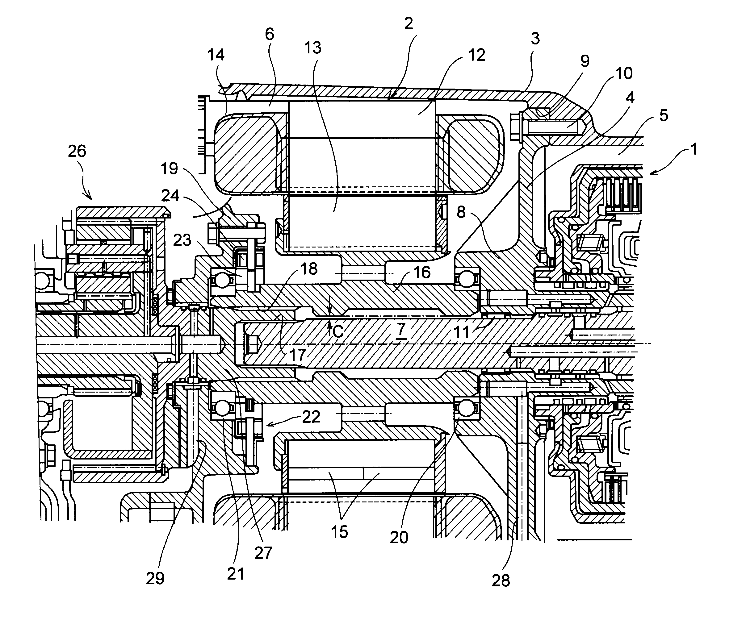
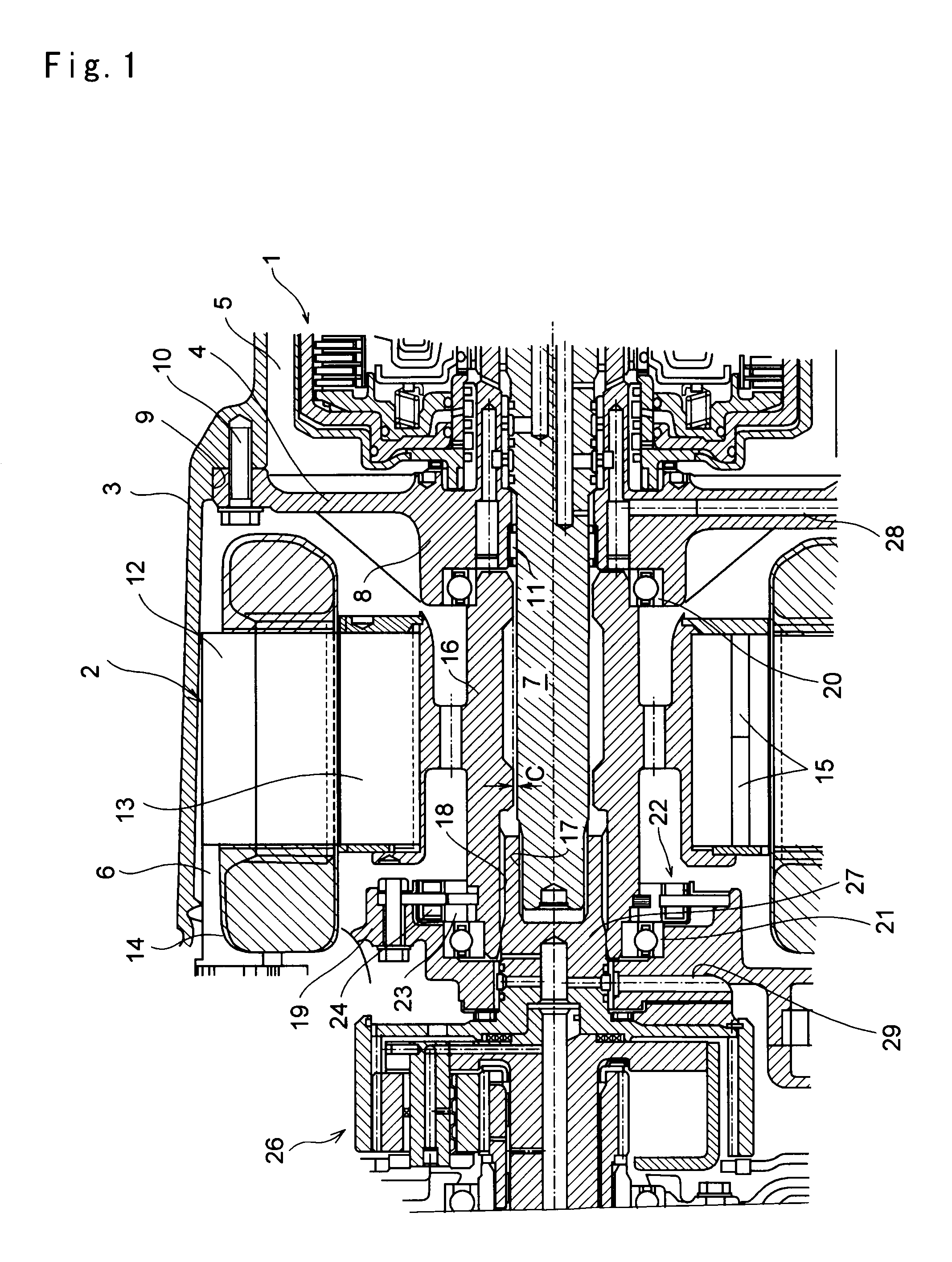
[0023]Next, this invention will be explained in connection with its specific example. FIG. 1 is a cross-sectional view partially showing a power transmission unit to which the invention is applied. As illustrated in FIG. 1, the power transmission unit comprises a mechanical transmission unit 1 and an electric motor 2. Those transmission unit 1 and electric motor 2 are housed in a casing 3. One of the open ends of the casing 3 (i.e., left side of FIG. 1) opens widely, and an open end of other side (i.e., right side of FIG. 1) opens narrowly to allow passage of a not shown output shaft therethrough. An internal space of the casing 3 is divided into two chambers 5 and 6 by a bulkhead 4 built inside of the casing 3. As shown in FIG. 1, the transmission unit 1 is housed in the right chamber 5, and the electric motor 2 is arranged adjacent to the bulkhead 4 in the left chamber 6.

[0024]A geared transmission mechanism, or a belt-type or toroidal type continuously variable transmission mecha...


PUM

PropertyMeasurementUnit
poweraaaaaaaaaa
torqueaaaaaaaaaa
circumferenceaaaaaaaaaa

Abstract

To improve a convenience in assembling a rotor of an electric motor of a power transmission unit comprising the electric motor and a transmission mechanism.
For this purpose, in the power transmission unit comprising an electric motor 2 having a rotor 13 arranged on an inner circumference of a stator 12 and concentrically with the stator 12 and a transmission mechanism 1 for transmitting power, a portion of a predetermined constructional element 7 of the transmission mechanism 1 protrudes toward the stator 12 or the rotor 13 side coaxially with the stator 12 or the rotor 13. The rotor 13 is loosely fitted onto an outer circumferential face of the protruding portion 7, and a clearance C is created between an outer circumferential face of the protruding portion 7 and an inner circumferential face of the rotor 13 into which a guide sleeve for guiding the rotor 13 in an axial direction is inserted.

Description

TECHNICAL FIELD[0001]This invention relates to a power transmission unit comprising a transmission mechanism and an electric motor increasing a torque inputted to the transmission mechanism and decreasing a torque outputted from the transmission mechanism, and to an assembling method thereof.BACKGROUND ART[0002]In the prior art, a unit composed of a combination of an internal combustion engine with an electric motor, a unit using an electric motor as a prime mover and so on are known as a power unit of a vehicle. In order to control a drive torque and speeds of the internal combustion engine and the electric motor, a transmission is employed in a vehicle having the power unit of those kinds. One example is disclosed in Japanese Patent Laid-Open No. 2003-127681. The system disclosed in Japanese Patent Laid-Open No. 2003-127681 is a hybrid vehicle drive system in which an internal combustion engine is connected with a carrier of a planetary gear mechanism, and a first motor / generator ...

Claims


Application Information

Patent Timeline
Patent Type & Authority Applications(United States)
IPC IPC(8): H02K15/16B60K6/26B60K6/36B60K6/40B60K6/405B60K6/445B60K6/547B60K17/04B60L50/16F16H57/021F16H57/023
CPCB60K6/26B60K6/365B60K6/40Y10T29/49879B60K6/547Y02T10/6239Y10T29/49009B60K6/445Y02T10/62
Inventor IHARA, HIROTATSUMIURA, TETSUYAKASUYA, SATORUKITO, MASASHI
Owner TOYOTA JIDOSHA KK
Why Eureka
Try Eureka