
Power amplifier having input ends combined in series and output ends combined in series

a power amplifier and series technology, applied in the field of power amplifiers, can solve the problems of large line loss, difficult design of power amplifiers, and inability to design power amplifiers easily, and achieve the effect of reducing the input impedance of power amplifiers and reducing the design difficulty

Active Publication Date: 2009-05-07
NAT TAIWAN UNIV
View PDF5 Cites 6 Cited by
  • Summary
  • Abstract
  • Description
  • Claims
  • Application Information

AI Technical Summary

Benefits of technology

[0006]In light of the foregoing drawbacks in the prior art, an objective of the present invention is to provid...

Problems solved by technology

However, since these transistors are connected in parallel with each other, currents flowing through the power amplifier are inevitably large, thereby causing a large line loss.
Moreover, the input and output impedances of the power amplifier are very small, thus making the design of the power amplifier more challenging and difficult.
However, since the input ends of the power amplifier are still combined in parallel with each other, the input impedance thereof is still too small to allow easy designing.
Although such power amplifier may have large input impedance, the parasitic effect of the transistors cannot be neglected when the power amplifier is operating in a high frequency.
As a result, the power combination efficiency of such power amplifier is greatly reduced.

Method used


Image

  • Power amplifier having input ends combined in series and output ends combined in series
  • Power amplifier having input ends combined in series and output ends combined in series
  • Power amplifier having input ends combined in series and output ends combined in series

Examples


Embodiment Construction

[0013]The present invention is described by the following specific embodiments. Those with ordinary skills in the arts can readily understand the other advantages and functions of the present invention after reading the disclosure of this specification. The present invention can also be implemented with different embodiments. Various details described in this specification can be modified based on different viewpoints and applications without departing from the scope of the present invention.

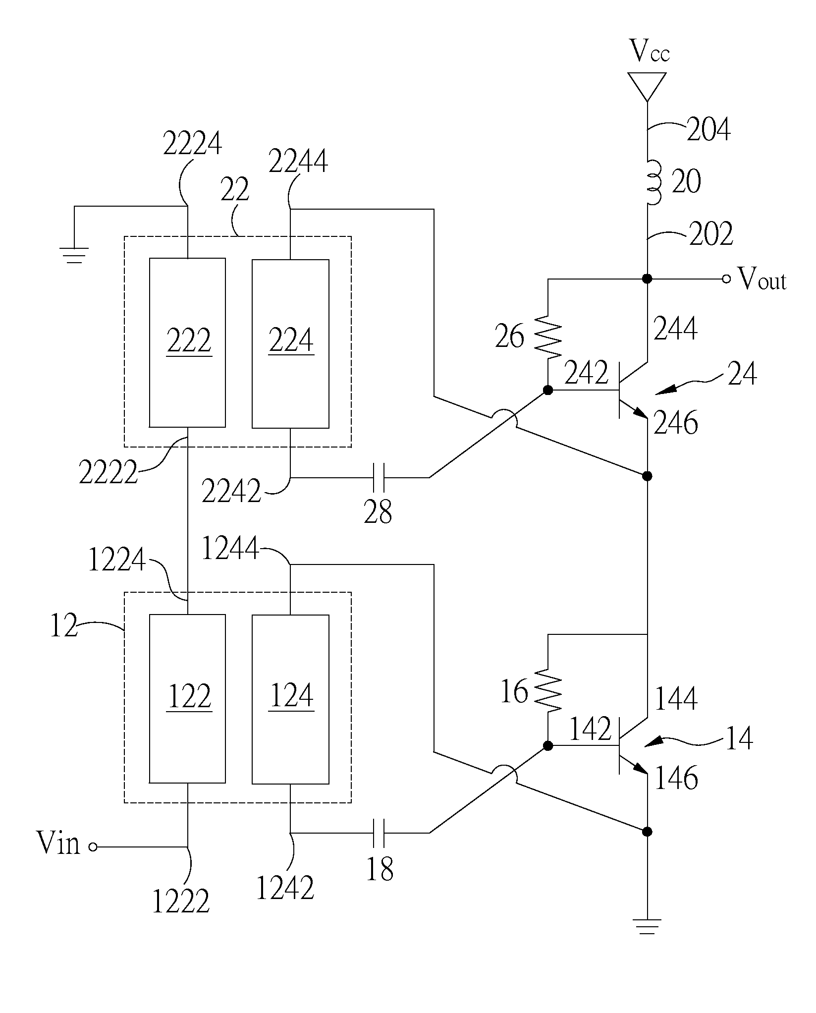
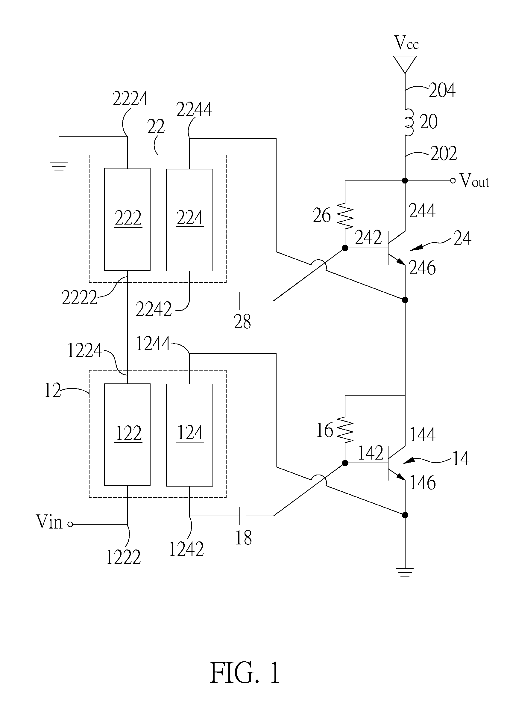
[0014]FIG. 1 is a circuit diagram of a power amplifier 10 according to a preferred embodiment of the present invention. Referring to FIG. 1, the power amplifier 10 includes a first transformer 12, a first transistor 14, a first resistor 16, a second transformer 22, a second transistor 24, a second resistor 26, and a bias circuit 20.

[0015]The first transformer 12 includes a first primary coil 122 and a first secondary coil 124. A first end 1222 of the first primary coil 122 is used to receive an ...


PUM


Abstract

A power amplifier includes a first transformer, a first transistor, a first resistor, a second transformer, a second transistor, a second resistor, and a bias circuit. The first transformer drives the first transistor. The second transformer drives the second transistor. The first transformer is connected in series with the second transformer. The first transistor is connected in series with the second transistor. Therefore, the power amplifier has input impedance and output power both greater than those of a conventional power amplifier.

Description

FIELD OF THE INVENTION[0001]The present invention relates to power amplifiers, and more particularly, to a power amplifier with input ends combined in series and output ends combined in series.BACKGROUND OF THE INVENTION[0002]Power amplifiers are often provided at a front end of a microwave communication system, for providing high output power. Limited by the rated breakdown voltage and operating current of transistors, the power amplifiers usually have to include a plurality of transistors so as to increase the operating voltage and current of the power amplifiers.[0003]“Microwave Transistor Amplifiers, Analysis and Design, 2nd edition” (Chapter 3, Upper Saddle River, N.J.: Prentice Hall, 1997, Guillermo Gonzalez) discloses a power amplifier having a plurality of transistors. The transistors have input ends connected in parallel with each other, and output ends connected in parallel with each other. As such, the input ends of the transistors have the same potential and current, and...

Claims


Application Information

Patent Timeline
IPC IPC(8): H03F3/68
CPCH03F1/34H03F3/19H03F3/211H03F3/45475H03F2203/45166H03F2200/273H03F2200/451H03F2200/534H03F2200/108
Inventor CHAO, SHIH-FONGTSAI, ZUO-MINWANG, HUEI
Owner NAT TAIWAN UNIV
Learn More