Fugitive Emissions Detection Devices

a technology of fugitive emissions and detection devices, which is applied in the direction of fluid tightness measurement, fire alarms, instruments, etc., can solve the problems of inconvenient and inexpensive use of existing systems, the amount of polluting emissions that are leaked directly into the atmosphere, and the inability to meet the needs of monitoring and monitoring, etc., to achieve convenient and inexpensive use

Inactive Publication Date: 2009-05-07
FUGITIVE EMISSIONS DETECTION DEVICES
View PDF1 Cites 2 Cited by
  • Summary
  • Abstract
  • Description
  • Claims
  • Application Information

AI Technical Summary

Benefits of technology

[0011]The present invention is also directed to a heretofore unknown adsorption detector. The preferred detector is comprised of a substrate, e.g., metal or ceramic, electrode elements, adsorbent particles, like carbon, of substantially the same size, and an elastomer or a binder type gas permeable material. Preferably, the detector is operated in a non-current saturated mode or in a linear region and can detect substances having a Van der Waals “a” constant of less than about 9. Optionally, if desired, the detector may include non-adsorbent particles. Further, if desired, the detector may include a temperature detector or sensor. In some systems, for example, smaller systems, an indicating cartridge can be used as the detector and signaler. For instance, chemical-treated granules affixed to paper or chemical granules will change color when a threshold emission occurs. The indicator material (or detector / signaler) is enclosed in a housing, like a cylinder, which is installed or connected to the enclosures of the present invention. It is the main object of the present invention to provide a monitoring system to detect emissions before any significant amounts reach the atmosphere which is both convenient and inexpensive to use.

Problems solved by technology

One of the major environmental concerns is the amount of polluting emissions which are leaked directly into the atmosphere due to the failure of present systems.
The existing systems are expensive and technically inadequate.

Method used


Image

  • Fugitive Emissions Detection Devices
  • Fugitive Emissions Detection Devices
  • Fugitive Emissions Detection Devices

Examples


Embodiment Construction

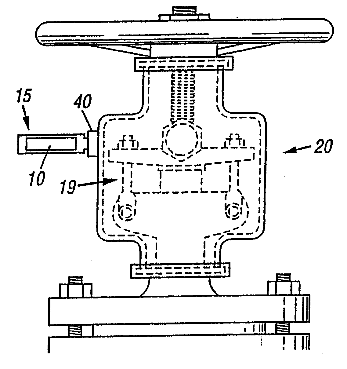
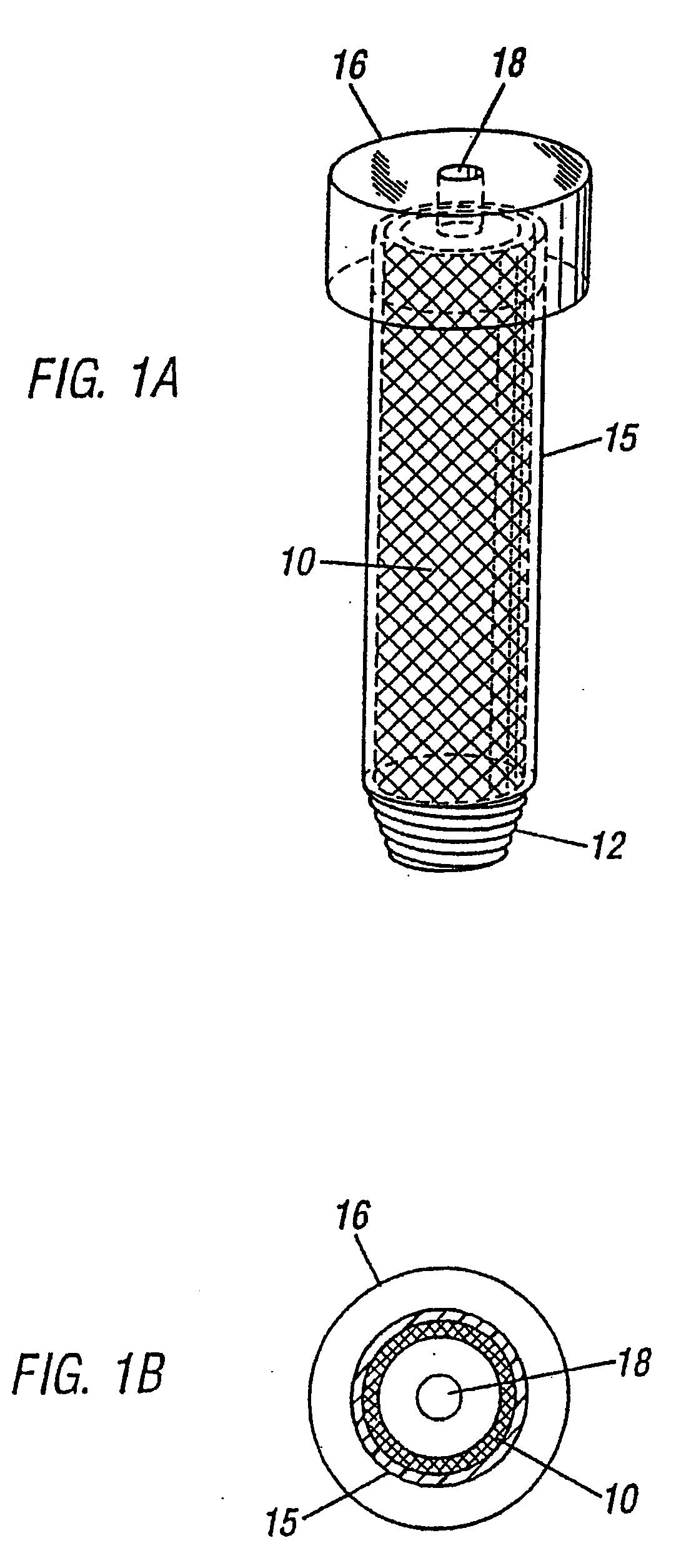
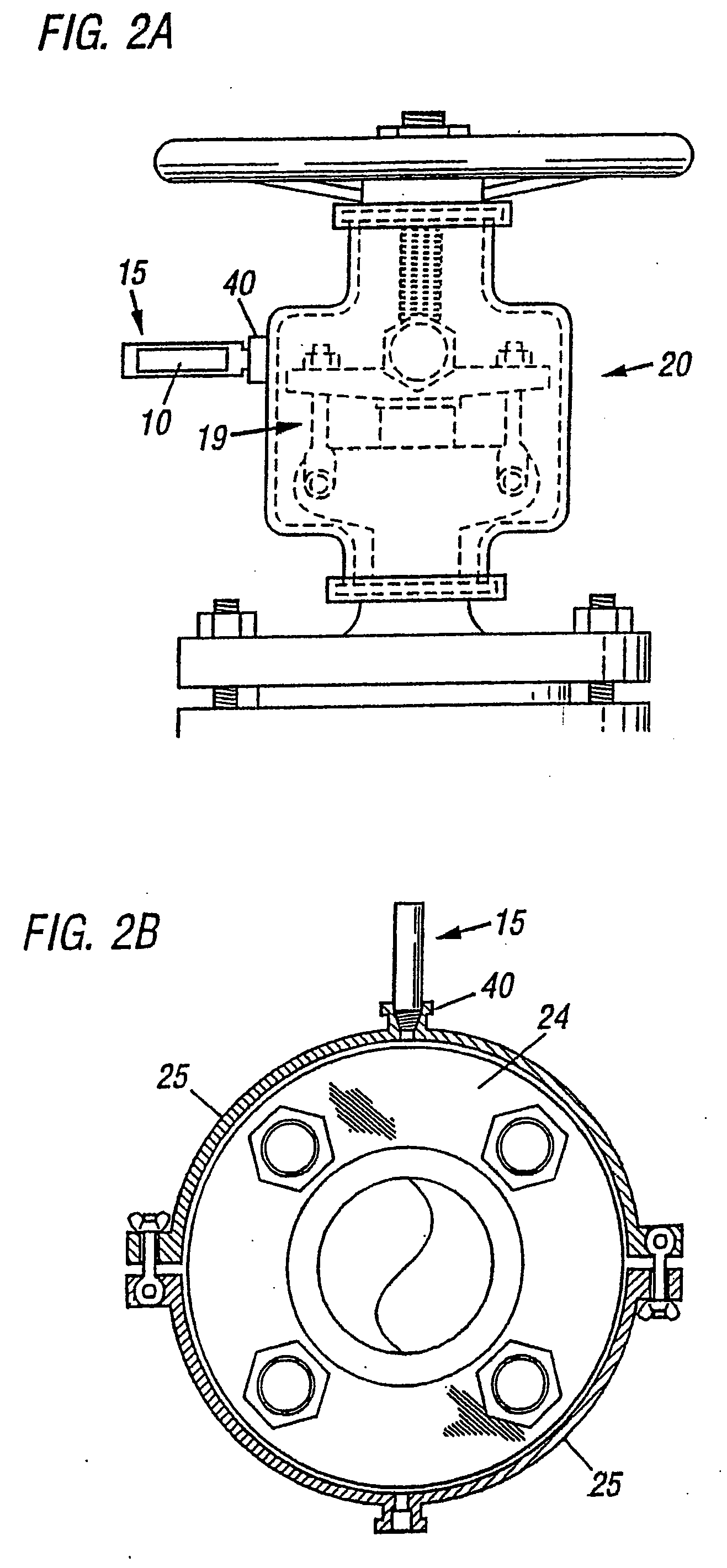
[0033]FIG. IA shows an emissions indicating strip 10 (a detector and signaler) contained within an acrylic or fiberglass cylinder 15. The emissions indicating strip 10 is chemically-treated paper, here shown in the shape of a tube; the paper discloses a color change when emissions react with the chemical present on the surface of the paper (for example, paper treated with litmus will show a color change from red to blue when exposed to ammonia). Similarly, chemically-treated granule detectors / signalers change color upon reaction with emissions, or emissions actuate a gas detector which would trip a relay and activate a light signaler to switch on, also within the acrylic cylinder. The lower portion of the cylinder 15 has threads 12 for insertion into a stuffing box enclosure coupling 30, or into a flange enclosure coupling 40. Cylinder cap 16 seals cylinder 15 and has a one-way cylinder cap vent 18 to relieve any pressure build-up from within the stuffing box enclosure or flange enc...


PUM


Abstract

The present invention relates to detection and alarm systems for predicting and detecting the location of spills, leaks, emissions, and / or pollution sources, i.e., unwanted fluid (liquid / gas) flow / escape, at refineries, e.g., oil and gas refineries, and plants, e.g., petrochemical, chemical, pharmaceutical, and food processing plants, and avoiding said unwanted flow / escape. According to one embodiment, said system comprises at least one detector, at least one battery powered radio frequency transmitter, preferably, according to one embodiment, a 900 megahertz spread spectrum transmitter, and a central processing location which, according to one embodiment, is preferably capable of handling up to 3000 points in a single cell site.

Description

CROSS REFERENCE TO RELATED APPLICATION[0001]This application is a continuation of U.S. patent application Ser. No. 10 / 736,324 filed Dec. 15, 2003; which is a continuation of U.S. patent application Ser. No. 10 / 369,926 filed on Feb. 18, 2003, now U.S. Pat. No. 6,722,185; which is a continuation of U.S. patent application Ser. No. 09 / 536,486 filed on Mar. 27, 2000, now U.S. Pat. No. 6,530,259; which is a continuation application of U.S. Ser. No. 09 / 199,234 filed on Nov. 24, 1998, now U.S. Pat. No. 6,041,645; which is a continuation of U.S. Ser. No. 08 / 836,927 filed on Aug. 13, 1996, now U.S. Pat. No. 5,979,227; which is a national application of PCT / US95 / 15064 filed on Nov. 17, 1995, and a continuation-in-part application of application Ser. No. 08 / 341,419 filed on Nov. 17, 1994, now U.S. Pat. No. 5,610,324; which is a continuation-in-part application of Ser. No. 08 / 148,997 filed on Nov. 8, 1993, abandoned.FIELD OF THE INVENTION[0002]The present invention is directed to the containmen...

Claims


Application Information

Patent Timeline
Patent Type & Authority Applications(United States)
IPC IPC(8): G08B21/00G08B1/08G01M3/04G01M3/18
CPCG01M3/042G01M3/045G01M3/184G01M3/185
Inventor LAWSON, RICK A.KELLY, MICHAEL S.
Owner FUGITIVE EMISSIONS DETECTION DEVICES
Why Eureka
Try Eureka