Backlight unit and liquid crystal display device

a liquid crystal display device and backlight technology, applied in the field of backlight units and liquid crystal display devices, can solve the problem that even color cannot be prevented from being displayed at the corners of the display surface, and achieve the effect of improving the uniformity of luminance and color

Inactive Publication Date: 2009-05-07
SHARP KK
View PDF7 Cites 21 Cited by
  • Summary
  • Abstract
  • Description
  • Claims
  • Application Information

AI Technical Summary

Benefits of technology

[0009]The present invention has been made in view of the above-mentioned state of the art. Preferred embodiments of the present invention provide a backlight unit and a liquid crystal display device, each capable of improving uniformity of a luminance and a color on a display surface.
[0010]The present inventors made various investigations of a backlight unit including a light source device including a first board on which a plurality of point light sources connected in series are arranged and a circuit board including a second board on which a driving circuit for the point light sources is arranged. The inventors discovered that if a fixed resistor for adjusting a luminance is connected in parallel to the point light source arranged on the end side, an amount of an electric current flowing into the point light source is reduced to decrease an amount of luminescence, and as a result, the corners and other regions of the display surface have substantially the same color tone and the uniformity of the luminance and the color on the display surface can be improved.

Problems solved by technology

However, the results of the study show that even if the above-mentioned measures are taken, uneven color cannot be sufficiently prevented from being displayed at the corners of the display surface because the point light sources such as LEDs have various light-emitting characteristics.

Method used


Image

  • Backlight unit and liquid crystal display device
  • Backlight unit and liquid crystal display device
  • Backlight unit and liquid crystal display device

Examples


first preferred embodiment

[0061]Steps of assembling a liquid crystal display device in accordance with the present preferred embodiment are mentioned below.

Production of LED Backlight Module (Light Source Device)

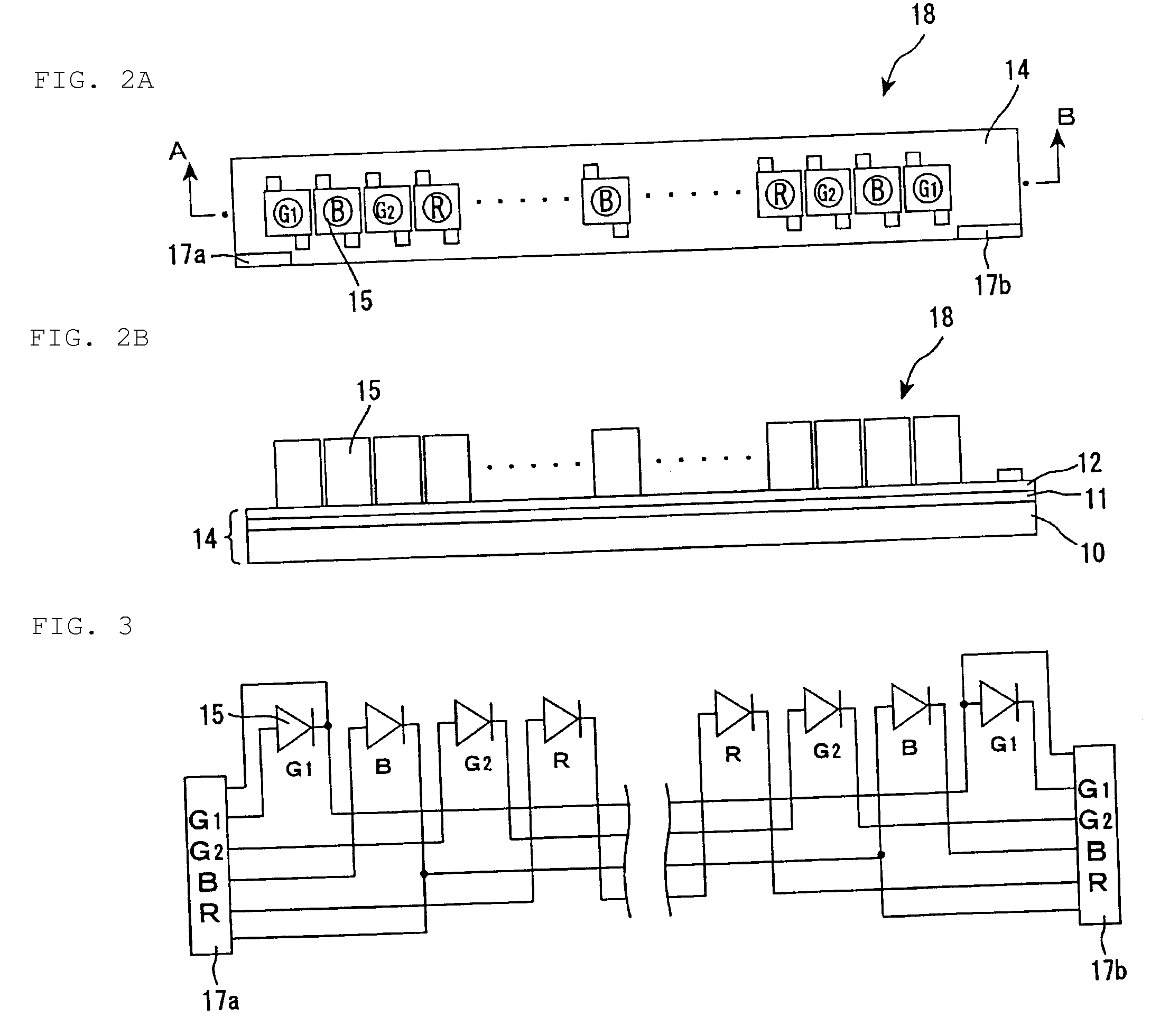
[0062]FIG. 2A is a planar view schematically showing a configuration of an LED backlight module in accordance with the first preferred embodiment. FIG. 2B is a cross sectional view schematically showing the LED backlight module taken along line A-B in FIG. 2A.

[0063]Light-emitting diodes (LEDs) 15, and connectors 17a and 17b were mounted on a FPC 14 formed by stacking a transparent insulating layer 11 with a thickness of about 80 μm and a copper foil layer 12 with a thickness of about 70 μm on an aluminum board 10, for example. The LEDs 15 included LEDs of three primary colors of a red LED (R-LED), a green LED (G-LED), and a blue LED (B-LED). Twelve R-LEDs, twenty-six G-LEDs, and thirteen B-LEDs were arrayed at regular intervals based on a color array pattern of green (G1), blue (B), green (G2), and r...

second preferred embodiment

[0073]Steps of assembling a liquid crystal display device in accordance with the present preferred embodiment are mentioned below. A direct LED backlight unit was used as the LED backlight unit in the present preferred embodiment.

Production of LED Backlight Module (Light Source Device)

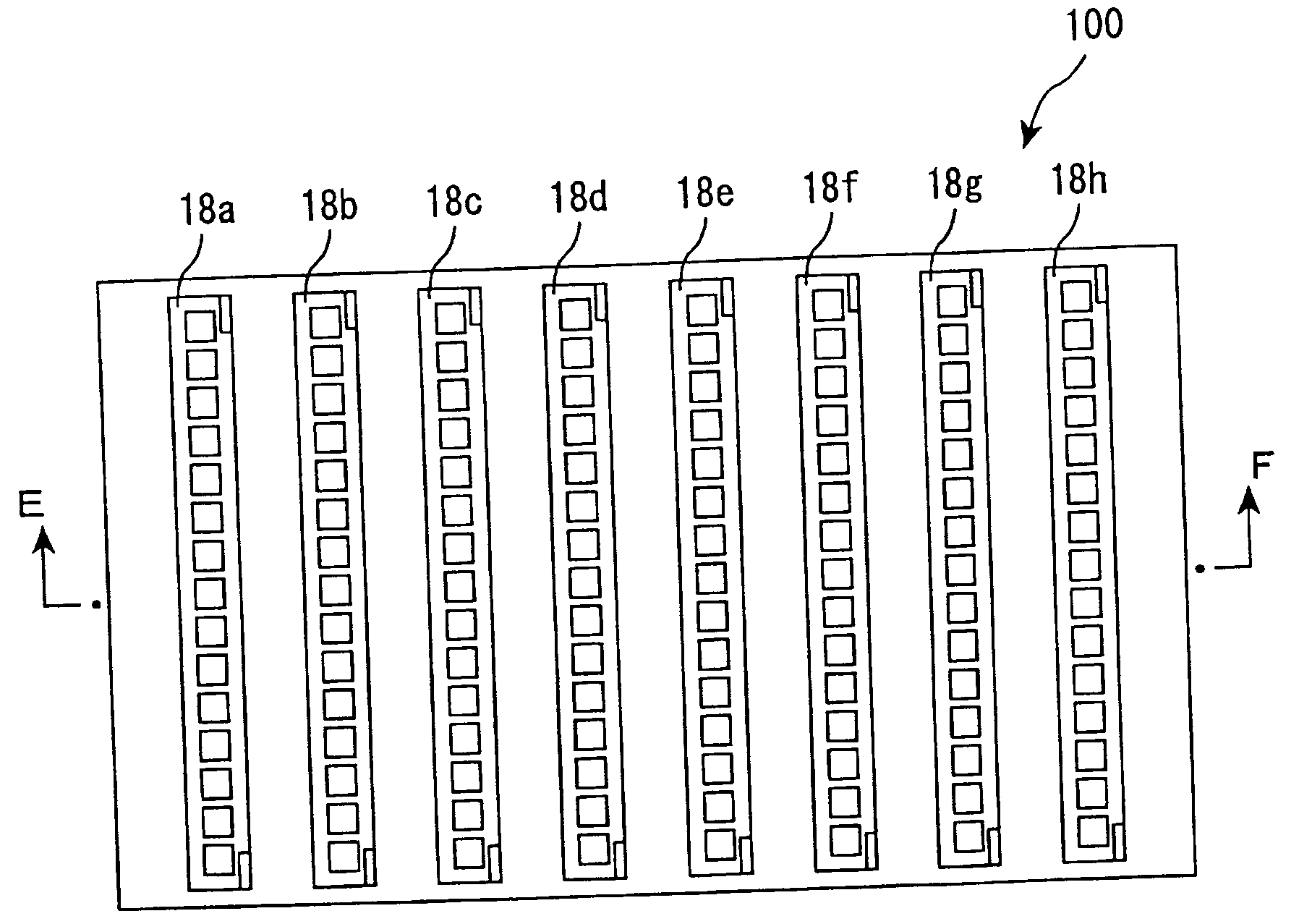
[0074]FIG. 6 is a view schematically showing a circuit for an LED backlight module in the second preferred embodiment. The LED backlight module in the present preferred embodiment preferably was produced in the same manner as in the first preferred embodiment, except that the G1-LEDs at right and left ends were connected to the connectors 17a and 17b, respectively, to be connected in parallel to variable resistors in a later step, as shown in FIG. 6. In the present preferred embodiment, eight LED backlight modules 18 were prepared and used as LED backlight modules 18a to 18h.

Production of LED Power Board (Circuit Board)

[0075]FIG. 7 is a planar view schematically showing a configuration of an LED power...


PUM

PropertyMeasurementUnit
thicknessaaaaaaaaaa
thicknessaaaaaaaaaa
resistanceaaaaaaaaaa

Abstract

A backlight unit and a liquid crystal display device improve uniformity of a luminance and a color of a display surface. The backlight unit includes a light source device and a circuit board, the light source device including a first board and a plurality of point light sources connected in series, the plurality of point light sources being arranged on the first board, and the circuit board including a second board, a driving circuit for the plurality of point light sources, and a variable resistance device, the driving circuit for the plurality of point light sources and the variable resistance device being arranged on the second board, wherein a resistance adjusting element of the variable resistance device is exposed to an outside, and at least one point light source arranged on an end side among the plurality of point light sources is connected in parallel to the variable resistance device.

Description

BACKGROUND OF THE INVENTION[0001]1. Field of the Invention[0002]The present invention relates to backlight units and liquid crystal display devices. More specifically, the present invention relates to a backlight unit mounted on a display device such as a liquid crystal display device, and a liquid crystal display device.[0003]2. Description of the Related Art[0004]A liquid crystal display device is a non-self-luminous display, and therefore, it generally includes a backlight unit on the back surface of a liquid crystal display panel in order to improve display visibility. This backlight unit includes a light source and its driving circuit as components. Based on the position where the light source is arranged, such backlight units are classified into a direct backlight unit in which the light source is arranged on the lower surface of a liquid crystal display panel and a side backlight unit in which the light source is arranged on a side surface of a liquid crystal display panel. T...

Claims


Application Information

Patent Timeline
Patent Type & Authority Applications(United States)
IPC IPC(8): G02F1/13357G09F13/08
CPCG02F1/133603H05B33/0821H05B33/086H05B33/0869H05K2201/10196H05K1/181H05K1/182H05K2201/10022H05K2201/10106H05K1/14H05B45/22H05B45/40H05B45/20H05B45/00
Inventor HAMADA, TETSUYA
Owner SHARP KK
Why Eureka
Try Eureka