
Method and system for controlling optical networks

a technology of optical networks and optical transmission networks, applied in the field of optical networks, can solve the problems of system availability of point systems, limited transmission distance, and limited length of optical spans, and achieve the effect of facilitating the selection and control of end-to-end paths

Active Publication Date: 2009-05-07
CIENA
View PDF2 Cites 24 Cited by
  • Summary
  • Abstract
  • Description
  • Claims
  • Application Information

AI Technical Summary

Benefits of technology

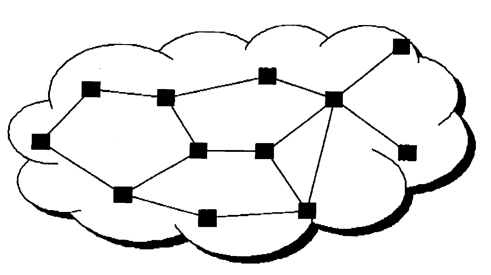
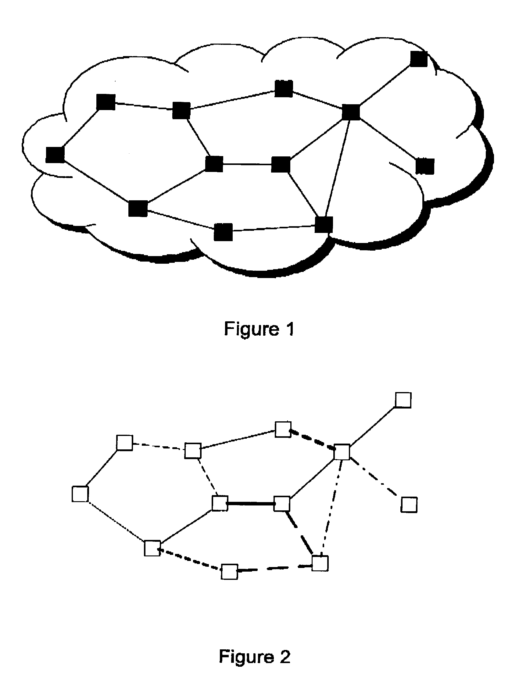
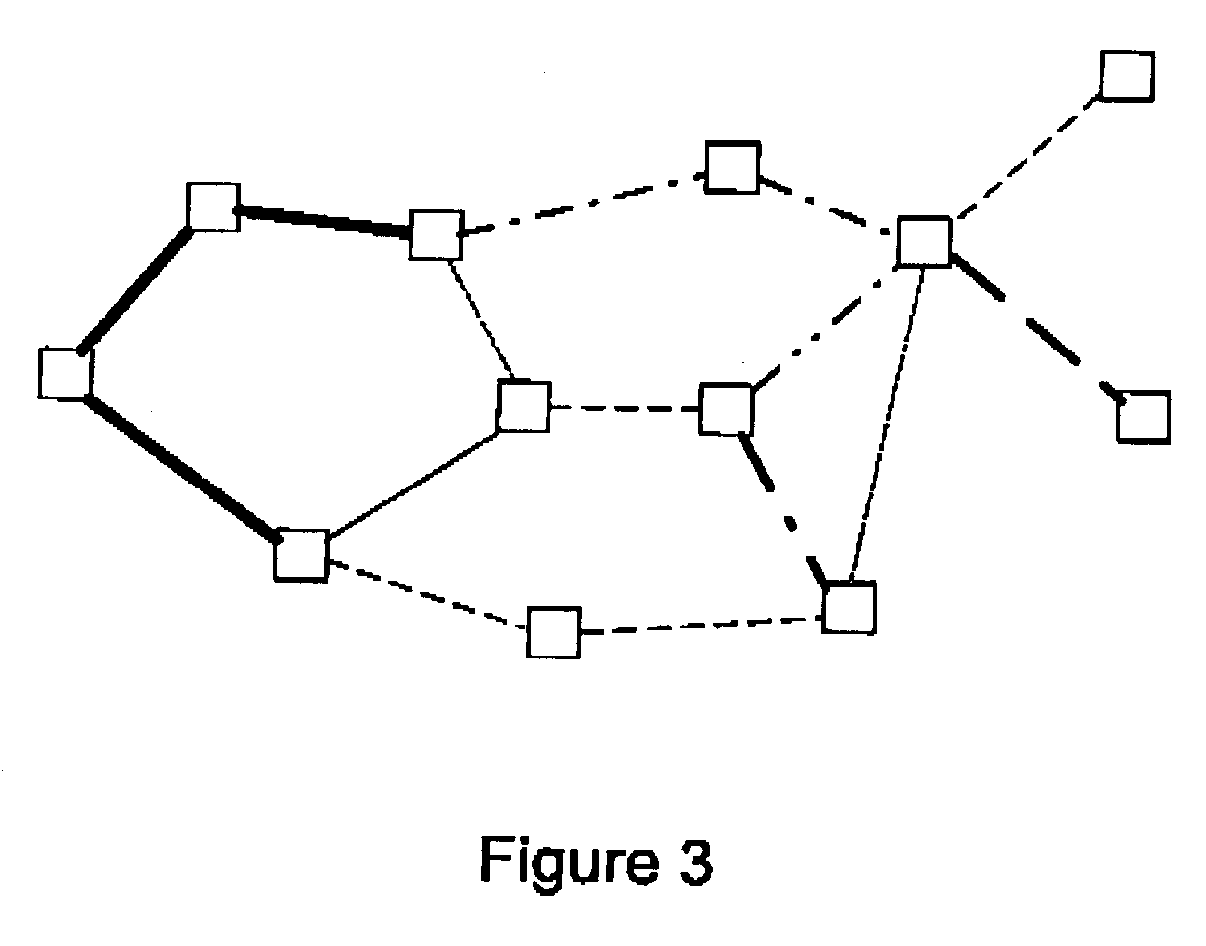
[0012]In a first aspect, the present invention provides an underlying control system for an optical network that is flexible and extensible by dividing an optical network into domains which can be considered system building blocks and which allows DWDM optical interworking between said domains. In an embodiment of the invention, a peer-to-peer discovery mechanism is used to transfer information between domains in order to facilitate the selection and control of the end-to-end path for an optical signal.
[0016]In addition such embodiments can have the domain controller first send a signal to neighboring domain controllers comprising an indication of the parameters or state it intends to change prior to implementing said change. This allows the domains to establish a filtering operation at a domain boundary where cascading effects can occur.

Problems solved by technology

The length of the optical span was limited mainly by the loss of the fibre.
The transmission distance (length of span multiplied by the number of spans) was now limited by the chromatic dispersion of the fibre and the noise of the optical amplifiers.
A major disadvantage of the point to point system is system availability.
If there is a failure of a piece of equipment or a cut of a fibre span, the system is immediately unavailable.
Ring based deployments are the norm for most high-availability deployments, however, the ring architecture does not always lend itself to the natural geographical layout of nodes in a service area.
Another problem that needs to be addressed is the growth of optical networks, for example to satisfy increasing demand, or to expand the geographic reach of the network, or to interconnect existing networks.
However this cannot be easily extended to scalable, extendible optical networks, such as optical transmission systems, including the optical amplifiers and the transmission fiber, act in such a way that actions taken on any one or set of channels is not independent of the other channels which are traversing the system.
However, Electrical interconnection of optical systems requires that all of the optical channels are demultiplexed and treated individually with electrical regenerators which is costly, requires high power consumption, and requires a great deal of space.

Method used


Image

  • Method and system for controlling optical networks
  • Method and system for controlling optical networks
  • Method and system for controlling optical networks

Examples


Embodiment Construction

[0044]In the following description, for purposes of explanation, numerous details are set forth in order to provide a thorough understanding of the present invention. However, it will be apparent to one skilled in the art that these specific details are not required in order to practice the present invention. In other instances, well-known electrical structures and circuits are shown in block diagram form in order not to obscure the present invention. For example, specific details are not provided as to whether the embodiments of the invention described herein are implemented as a software routine, hardware circuit, firmware, or a combination thereof.

[0045]Embodiments of the invention may be represented as a software product stored in a machine-readable medium (also referred to as a computer-readable medium, a processor-readable medium, or a computer usable medium having a computer readable program code embodied therein). The machine-readable medium may be any suitable tangible medi...


PUM


Abstract

An optical control system is described which is capable of maintaining and optimizing a fiber-optic transport system within it's domain of control while interacting with other optical systems which are controlled independently. This allows the optical system to be incorporated as a building block into a larger optical network in a relatively arbitrary fashion. This provides an underlying control system for a non-linear system like optics network that is flexible and extensible.

Description

CROSS REFERENCE TO RELATED APPLICATIONS[0001]This application claims the benefit of priority of U.S. Provisional Patent Application No. 60 / 745,807 filed Apr. 27, 2006, which is incorporated herein by reference.FIELD OF THE INVENTION[0002]The present invention relates generally to optical networks. More particularly, the present invention relates to scalable, flexible optical transmission networks, and methods and systems for controlling same.BACKGROUND OF THE INVENTION[0003]The simplest optical system is a point to point system. This can be unidirectional or bidirectional. These were the first optical systems to be deployed even before the advent of optical amplification. Single wavelengths modulated with the information being transmitted would be coupled into and out of an optical fiber. The optical signal was then converted to / from electrical on either end of the fiber span, a practice called regeneration. The length of the optical span was limited mainly by the loss of the fibre....

Claims


Application Information

Patent Timeline
Patent Type & Authority Applications(United States)
IPC IPC(8): H04B10/20H04L69/14
CPCH04J14/0201H04J14/0241H04J14/0284H04J14/0227
Inventor BOERTJES, DAVID W.SMIEDEMA, DAVIDBERG, LORENPOULIN, FREDERICBOWNASS, DAVIDPALMER, ROBERTHINDS, MARKHIRIDJEE, MICHAELSEYDNEJAD, SAEID
Owner CIENA
Learn More