Coating system and coating method

a coating system and coating technology, applied in the field of coating systems and coating methods, can solve the problems of large and complex coating facilities, conventional coating apparatuses failing to meet the demand for a wide range in recent years, and achieve the effect of compact coating facilities and efficient coating processes

Inactive Publication Date: 2009-05-07
HONDA MOTOR CO LTD
View PDF1 Cites 5 Cited by
  • Summary
  • Abstract
  • Description
  • Claims
  • Application Information

AI Technical Summary

Benefits of technology

[0007]It is an object of the present invention to provide a coating system and a coating method, which are capable of realizing a compact coating facility, lending themselves to the production of vehicles in many types and small quantities, while also performing an efficient coating process.

Problems solved by technology

To satisfy these various coating requirements, many coating lines need to be provided, resulting in a considerably large and complex coating facility.
Conventional coating apparatuses thus fail to meet demands in recent years for a wide variety of vehicle coating colors and trends toward the production of vehicles in many types and small quantities.

Method used


Image

  • Coating system and coating method
  • Coating system and coating method
  • Coating system and coating method

Examples


first embodiment

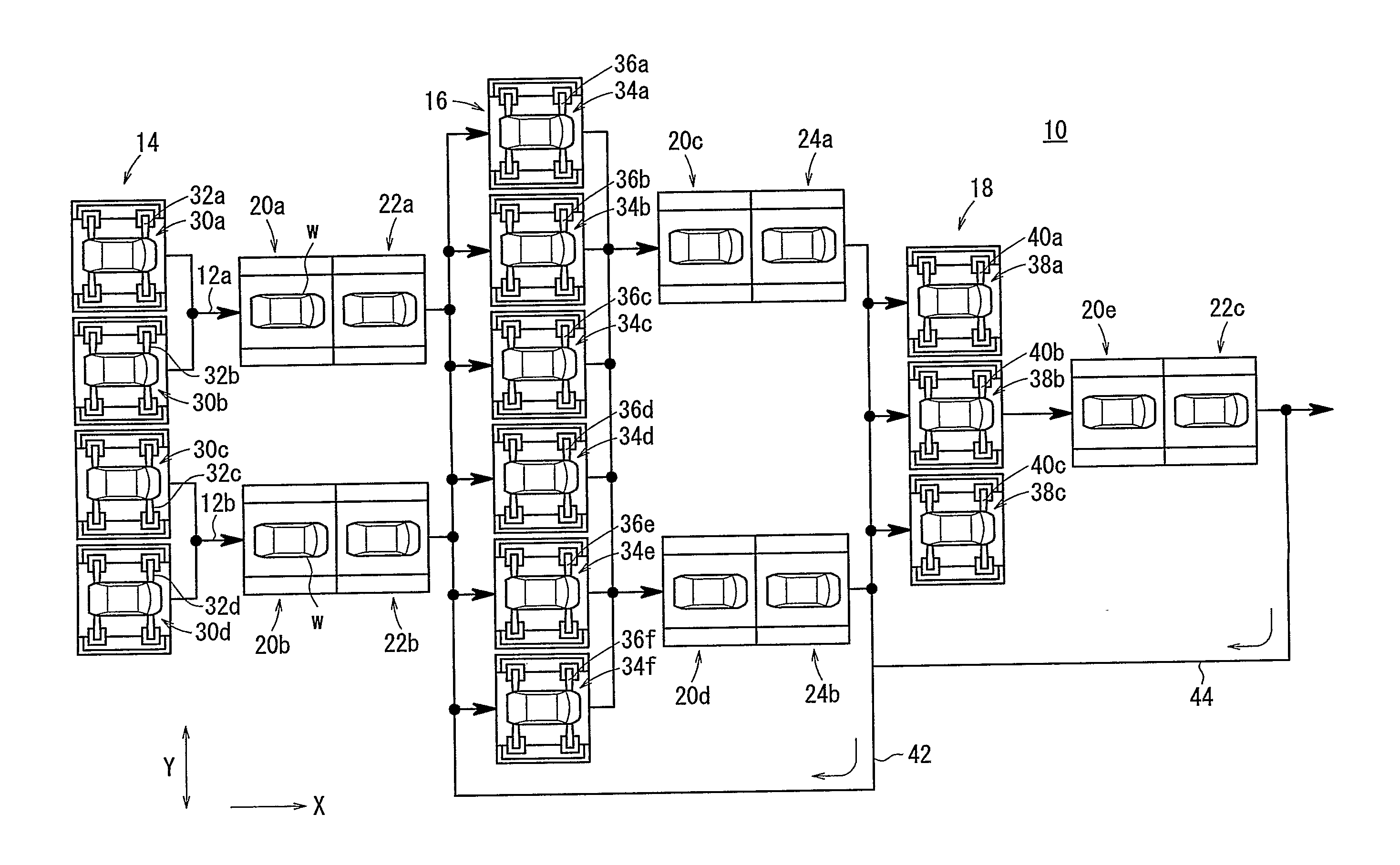
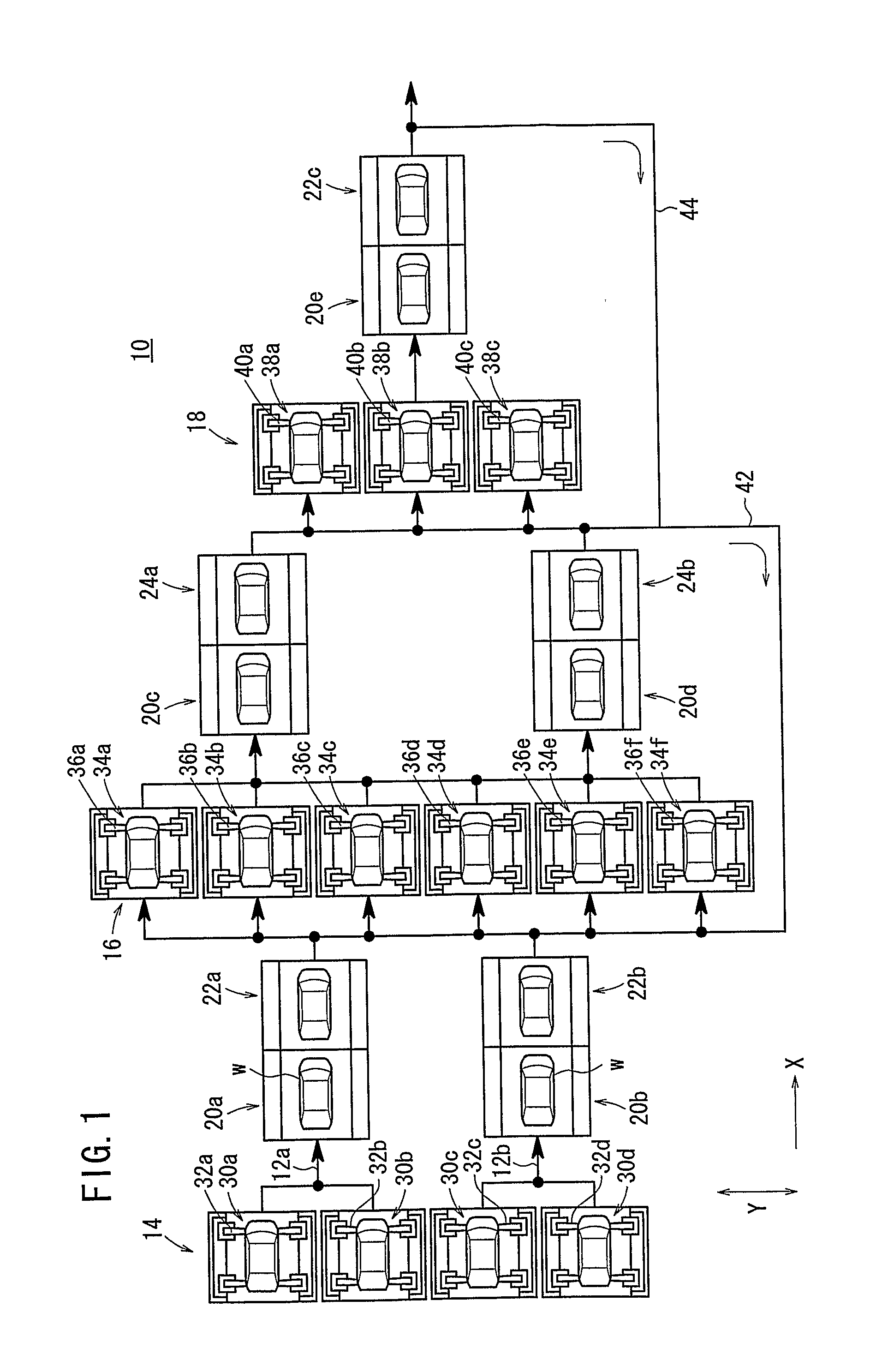
[0034]FIG. 1 shows a schematic plan view of a coating system 10 according to the present invention.

[0035]As shown in FIG. 1, the coating system 10 includes a first coating line 12a and a second coating line 12b, which extend in parallel to each other in a coating flow direction, i.e., in the direction indicated by the arrow X. The first coating line 12a and the second coating line 12b are made up of an intermediate coat applying process 14, an overcoat applying process 16, and a clear coat applying process 18, which are successively arranged downstream along the coating flow direction.

[0036]The first coating line 12a includes a first setting unit 20a and a first drying furnace (heating unit) 22a disposed between the intermediate coat applying process 14 and the overcoat applying process 16. Similarly, the second coating line 12b includes a second setting unit 20b and a second drying furnace 22b disposed between the intermediate coat applying process 14 and the overcoat applying proc...

second embodiment

[0091] the intermediate coat applying process 84 having the first through fourth intermediate coat applying stations 30a through 30d, the overcoat applying process 86 having the first through sixth overcoat applying stations 34a through 34f, and the clear coat applying process 88 having the first through third clear coat applying stations 38a through 38c, are disposed in parallel to each other across the coating line 82.

[0092]The coating system 80 thus configured makes it possible to adjust the coating time depending on coating specifications when the number of coating cycles is changed. By reducing the tact time in this manner, reductions in throughput of the coating system 80 can easily be avoided. The coating system 80 also makes it possible to change setups quickly and easily in order to change coating conditions, e.g., coating colors.

[0093]According to the second embodiment, the number of stations that make up each of the intermediate coat applying process 84, the overcoat appl...

third embodiment

[0105] since the vehicle body W that has been polished by the wet sanding station 102 is dried by the first preheating unit 24a, the coating system 100 does not require a dedicated drying furnace, since the first preheating unit 24a itself functions as a drying furnace. Therefore, the coating system 100 is highly economical.


PUM


Abstract

A coating system includes an intermediate coat applying process, an overcoat applying process, and a clear coat applying process, which are disposed successively along a coating flow direction. The intermediate coat applying process includes first through fourth intermediate coat applying stations through, which are disposed in parallel to each other across a coating line. The overcoat applying process includes first through sixth overcoat applying stations through, which are disposed in parallel to each other across the coating line. At least each of the first through third overcoat applying stations through has a plurality of coating robots for applying coats having different colors.

Description

TECHNICAL FIELD[0001]The present invention relates to a coating system and a coating method, which have at least an intermediate coat applying process and an overcoat applying process, for coating portions of an outer panel and an inner panel of a workpiece to be coated.BACKGROUND ART[0002]Coating production lines for coating workpieces, e.g., vehicle bodies, have a rust-prevention undercoat applying process (electrodepositing process), an intermediate coat applying process, an overcoat applying process, and a clear coat applying process for coating white bodies, and also have a baking process between any successive two of the foregoing coating processes.[0003]There has been proposed a coating apparatus for use in such a coating line for purposes of reducing the number of coating robots used and for saving kinetic energy supplied to each of the coating booths, i.e., coating stations (see Japanese Patent Application No. 2001-129449).[0004]As shown in FIG. 16 of the accompanying drawi...

Claims


Application Information

Patent Timeline
Patent Type & Authority Applications(United States)
IPC IPC(8): B05D7/00B05C11/00B05B16/00
CPCB05B13/02B05D7/56B05D7/52B05B13/0452B05B13/0221B05B13/0278B05B16/00
Inventor NAKAZONO, DAISUKE
Owner HONDA MOTOR CO LTD
Why Eureka
Try Eureka