Nuclear waste removal system and method using wet oxidation

Active Publication Date: 2009-05-07
AREVA NP INC
View PDF10 Cites 4 Cited by
  • Summary
  • Abstract
  • Description
  • Claims
  • Application Information

AI Technical Summary

Benefits of technology

[0010]An object of the present invention is to provide effective and efficient waste removal usin

Problems solved by technology

These processes are used on the primary coolant loop (PCL) of the nuclear power plant for purpos

Method used


Image

  • Nuclear waste removal system and method using wet oxidation
  • Nuclear waste removal system and method using wet oxidation

Examples


Embodiment Construction

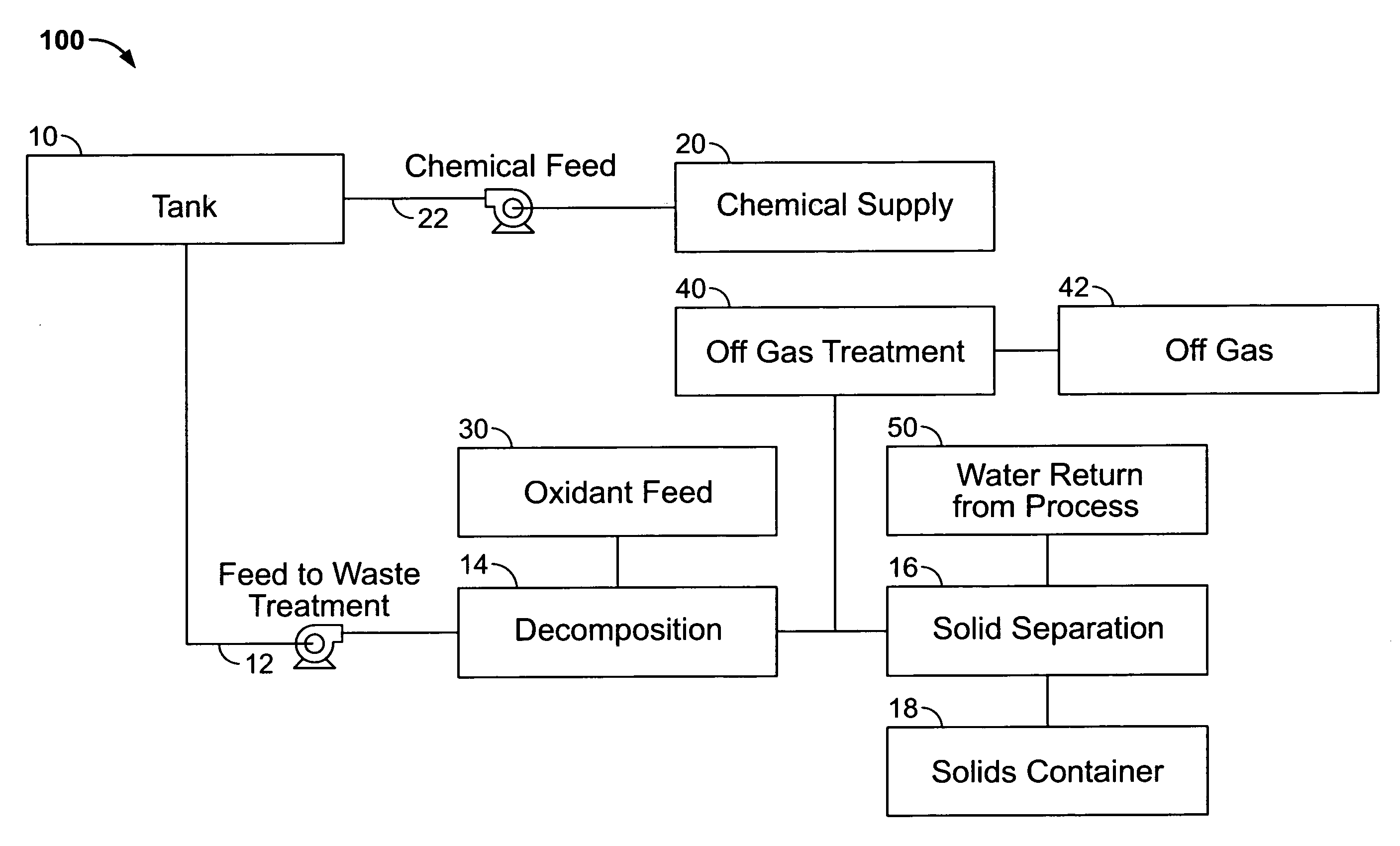
[0029]FIG. 1 shows schematically a chemical cleaning system 100. A tank 10, or other component with wastes to be cleaned, for example, heat transfer equipment or secondary piping system, for example, as disclosed in U.S. Patent Publication No. 2007 / 0153957 and U.S. Pat. No. 6,865,244 which are hereby incorporated by reference, is located outside of a primary coolant loop of a nuclear reactor. The primary coolant loop may be running, while chemical cleaning system 100 is employed.

[0030]Tank 10 may include tank wastes, such as deposits and sludge, which need to be removed. Tank wastes may include nuclear waste including copper, aluminum, sodium and iron materials. Tank 10 receives oxalic acid based chemicals from a chemical feed 22 connected to a chemical supply 20. The oxalic acid based chemicals soak in tank 10. Oxalic acid based chemicals may also be agitated in tank 10, for example, by circulation or gas sparging. Oxalic acid based chemicals may be added to chemical supply 20 dire...


PUM


Abstract

Methods for removing nuclear waste from a component are provided. In one embodiment, the method includes the steps of supplying oxalic acid to the nuclear waste on the component to form an oxalic acid/waste solution, feeding the oxalic acid/waste solution from the component, feeding an oxidant to the oxalic acid/waste solution to form carbon-dioxide, water and a precipitate, and separating the precipitate from the water. A system for removing nuclear waste is also provided.

Description

[0001]The present invention relates generally to components containing nuclear waste and more particularly to removing such waste from the components. Nuclear waste as defined herein is unwanted deposits, sludges, or salts that reside in a tank, vessel or heat exchanger that are generated during normal operation of a nuclear power plant or other nuclear materials facility.BACKGROUND[0002]U.S. Pat. No. 5,960,368 discloses a “wet” oxidation process for reducing the volume of low level radioactive and mixed waste to enable the waste to be more economically stored in a suitable repository, and for placing the waste into a form suitable for permanent disposal.[0003]U.S. Pat. No. 6,444,276, hereby incorporated by reference, discloses a method for decontaminating a surface that includes the steps of bringing a surface of a component formed of an unalloyed steel or a low-alloy steel into contact with a solution containing an oxalic acid for dissolving a contaminated layer from the component...

Claims


Application Information

Patent Timeline
IPC IPC(8): G21F9/06G21C1/00
CPCG21F9/06
Inventor JONES, III, SIDNEY DENNISBEATTY, RAYREMARK, JOHNHUDSON, WESLEY
Owner AREVA NP INC
Why Eureka
Try Eureka