Lower power disk array as a replacement for robotic tape storage

a technology of robotic tape storage and low power consumption, applied in the direction of instruments, power supply for data processing, sustainable buildings, etc., can solve the problems of increasing the cost of maintenance, increasing the difficulty of robotic tape storage access, and increasing the difficulty of improving the access to robotic tape storag

Inactive Publication Date: 2009-05-07
TEMPEST MICROSYST INC
View PDF25 Cites 27 Cited by
  • Summary
  • Abstract
  • Description
  • Claims
  • Application Information

AI Technical Summary

Benefits of technology

[0011]The controller, which can be programmed in software or in hardware, effects transition of a storage device from a power-off mode to a power-on mode upon receipt of a request for access to that storage device, for example, for reading data from or writing data to that storage device, i.e., a read / write request. When storage devices are disks, this approach effectively treats the disks as inexpensive tape drives.

Problems solved by technology

Currently, large scale data warehousing is typically implemented by employing tape media, which suffer from long access latency, namely, the time required for loading the tape and other associated access times. In addition, robotic tape systems are bulky and expensive to maintain.
Since the latency period for access to database items located in a tape archive is typically on the scale of tens to hundreds of seconds, a system overload frequently arises when a database search requires access to data located on many or all of the tapes in a library.
Improving robotic tape storage access presents a challenging problem.
These approaches, however, can not eliminate the fundamental limitations arising from tape access latency.
Current commodity disk drive units are only marginally more costly than tape media and will be less costly within a few years, if current trends continue.
However, disk-based systems having very large storage capacities, for example, hundreds of Terabytes, are very costly, and offer short retention life in comparison to tape.
However, similar to SAN, NAS devices can also be costly.

Method used


Image

  • Lower power disk array as a replacement for robotic tape storage
  • Lower power disk array as a replacement for robotic tape storage
  • Lower power disk array as a replacement for robotic tape storage

Examples


Embodiment Construction

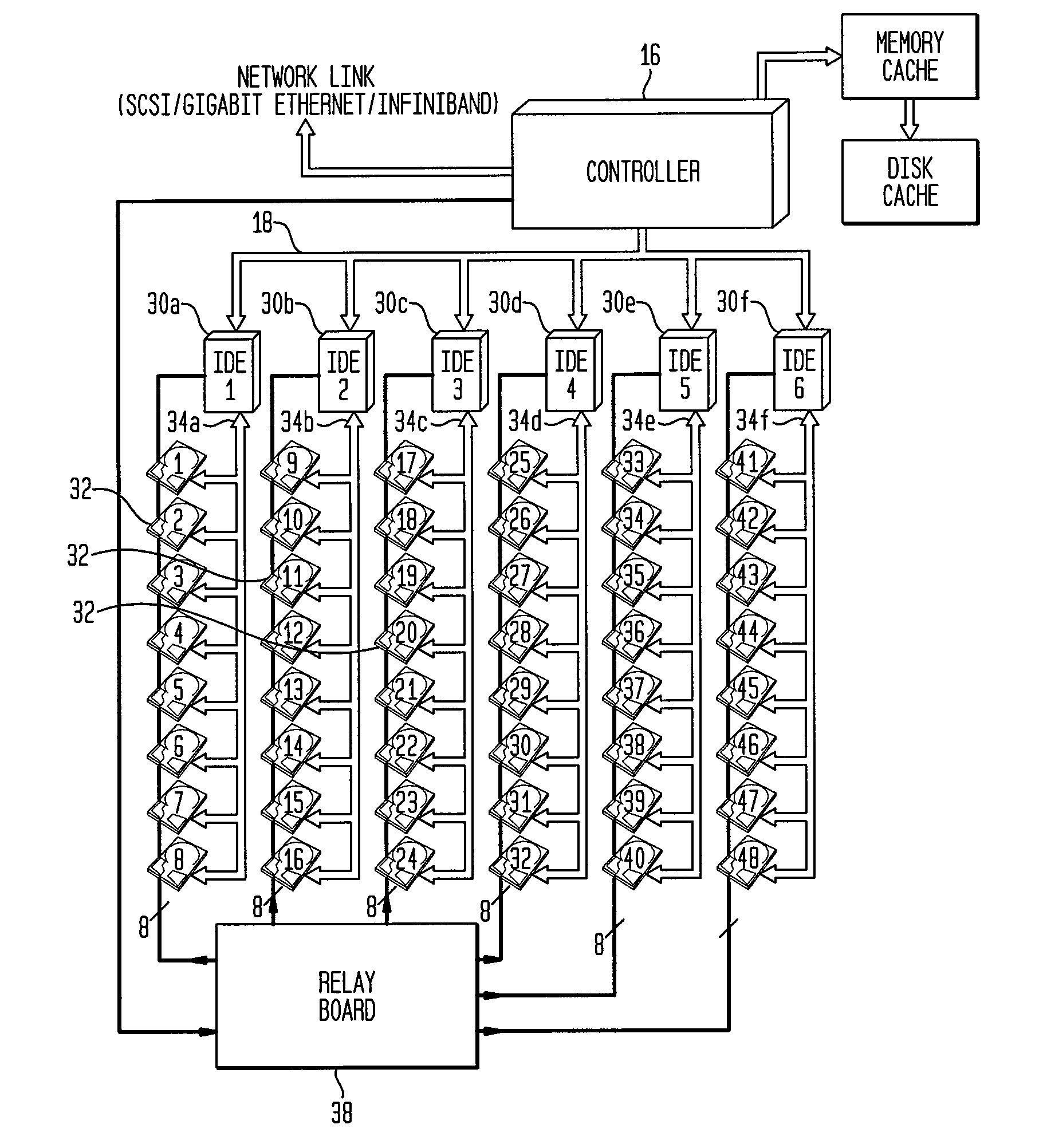
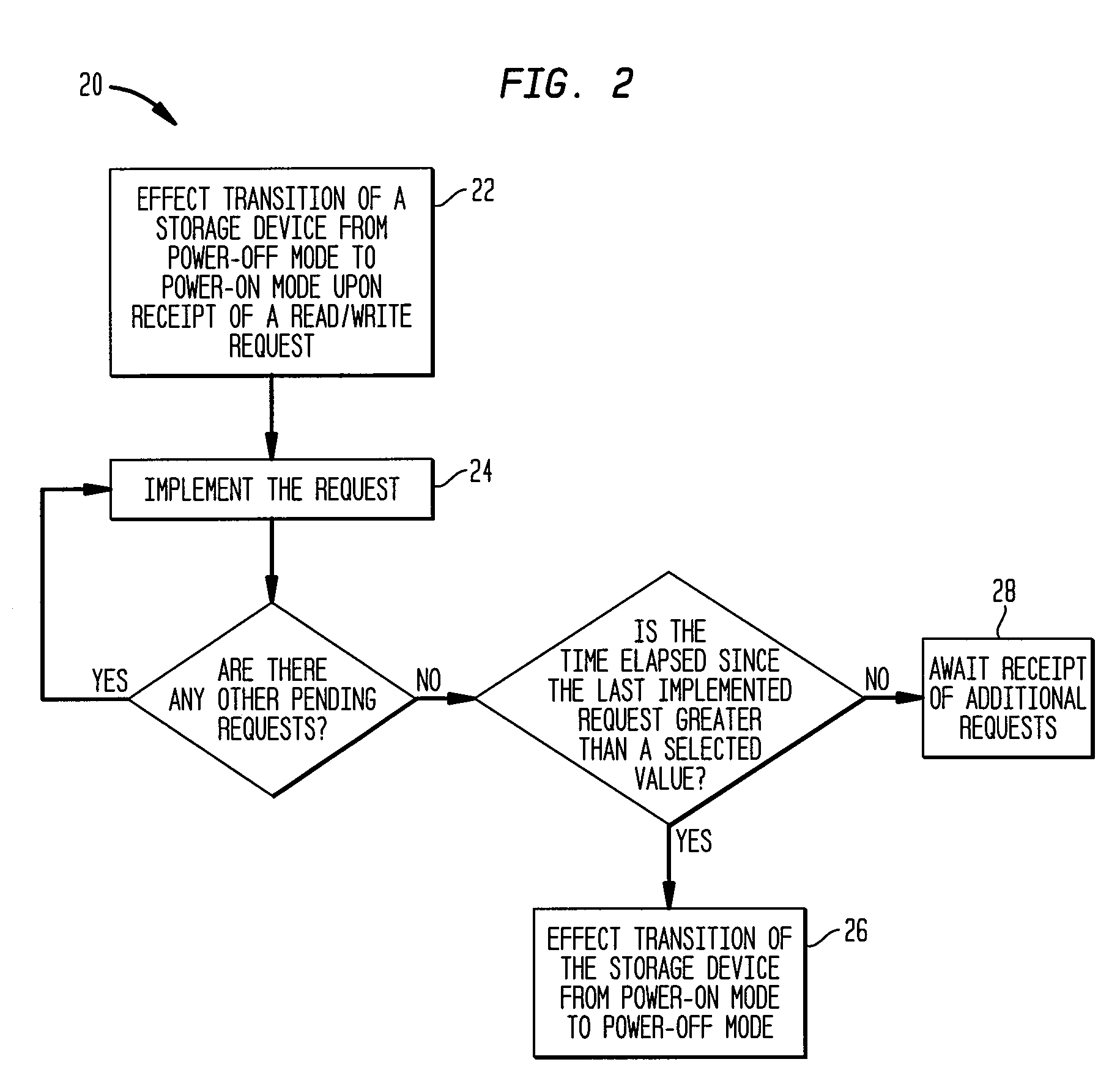
[0025]The present invention provides systems and methods for cost-effective storage and retrieval of a large amount of data while minimizing physical space required for such storage. As discussed in more detail below, a system of the invention can include a plurality of selected storage media, e.g., disks, which can be, for example, packed in an enclosure in close proximity of one another. Each storage medium is normally in a power-off state in order to alleviate the thermal load of the system. A controller is utilized to transition a selected one of the storage media from a power-off mode into a power-on mode in order to read data from and / or write data to that storage medium.

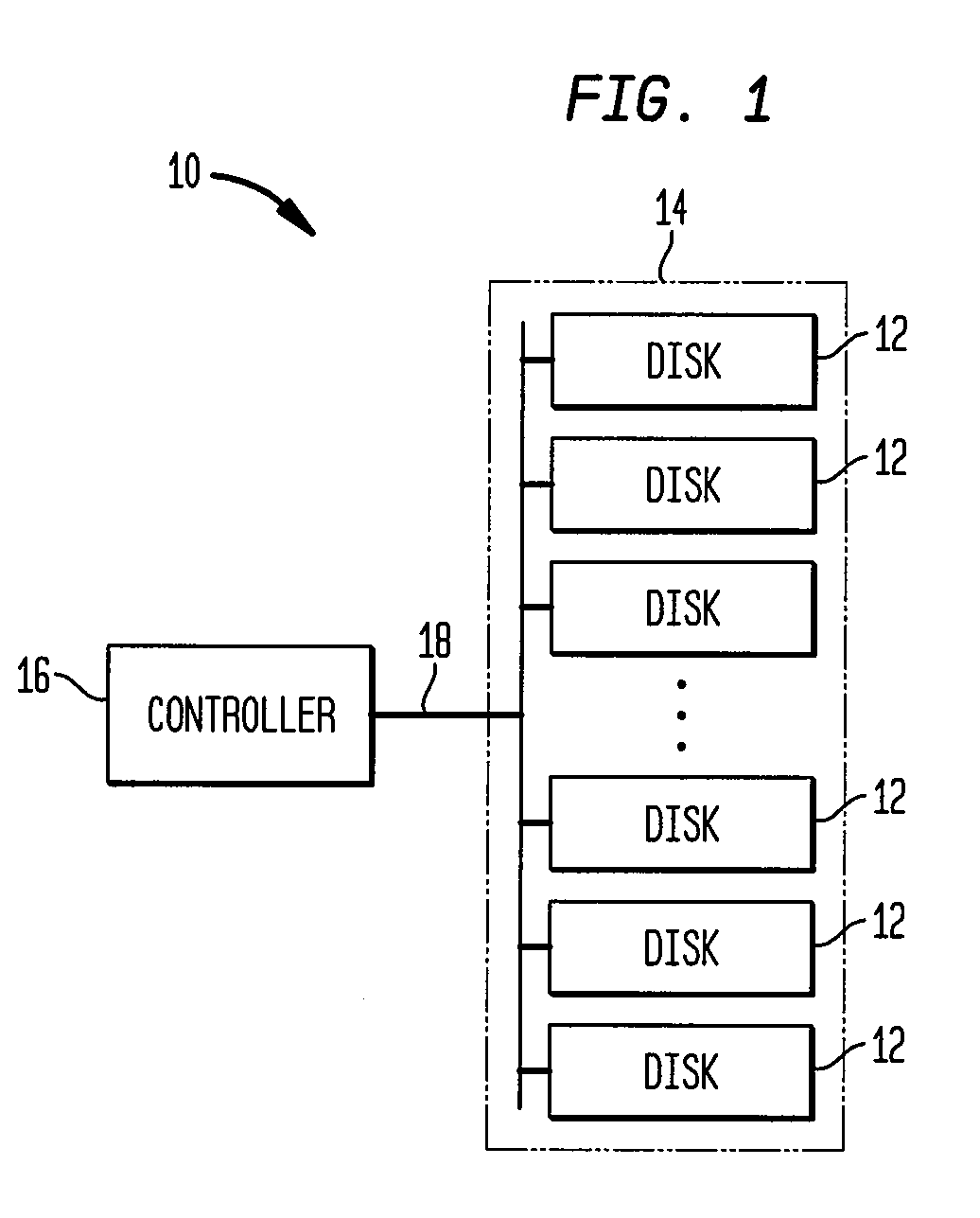
[0026]With reference to FIG. 1, an exemplary data storage system 10 according to the teachings of the invention includes a plurality of storage devices 12, for example, disks, provided in an enclosure 14, and a controller 16 that can communicate with the storage devices 12 via, for example, a bus 18. The contr...


PUM


Abstract

The present invention provides methods and systems for storage of data. In one aspect, the invention provides a data storage system that includes a plurality of storage devices, such as, disks, for storing data, and a controller that implements a policy for managing distribution of power to the storage devices, which are normally in a power-off mode. In particular, the controller can effect transition of a storage device from a power-off mode to a power-on mode upon receipt of a request for reading data from or writing data to that storage device. The controller further effects transition of a storage device from a power-on mode to a power-off mode if no read / write request is pending for that storage device and a selected time period, e.g., a few minutes, has elapsed since the last read / write request for that storage device.

Description

RELATED APPLICATIONS[0001]This application is a continuation of U.S. patent application Ser. No. 10 / 394,964, entitled “A Lower Power Disk Array As A Replacement For Robotic Tape Storage,” filed Mar. 21, 2003, which is herein incorporated by reference.FEDERALLY SPONSORED RESEARCH[0002]This invention was made with government support awarded by Department of Energy under Contract Number DE-FG03-01ER83315. The government has certain rights in the invention.BACKGROUND[0003]The present invention relates to methods and systems for storing data, and more particularly, to cost-effective methods and systems for storage and retrieval of a large amount of data, e.g., in a range of tens to hundreds of Terabytes.[0004]The volume of data generated by business processes in variety of organizations is increasing exponentially with time. Most industrial and business processes are far more efficient in generating digital data than in utilizing it. As a result, the demand for long-term data storage and...

Claims


Application Information

Patent Timeline
Patent Type & Authority Applications(United States)
IPC IPC(8): G06F1/32G06F12/00G06F3/06
CPCG06F1/3221G06F1/3268Y02B60/1246G06F2003/0694G06F2003/0697G06F3/0601G06F3/0664Y02D10/00
Inventor FISK, IANMOJAVER, MICHAEL
Owner TEMPEST MICROSYST INC
Why Eureka
Try Eureka