Hydraulic brake lever

a technology of hydraulic brakes and levers, which is applied in the direction of cycle brakes, braking systems, cycle equipments, etc., can solve the problems of troublesome oil supply, high manufacturing cost, and inability to achieve automatic oil supply, so as to facilitate oil-filling and reduce manufacturing costs.

Inactive Publication Date: 2009-05-14
HSIN TECH SHENZHEN
View PDF7 Cites 11 Cited by
  • Summary
  • Abstract
  • Description
  • Claims
  • Application Information

AI Technical Summary

Benefits of technology

[0007]Embodiments of the present invention provides a hydraulic brake level that can reduce the manufacturing cost and facilitate the oil supply to the reservoir.
[0010]Among others, the illustrated hydraulic brake lever has the following advantages: the position of oil reservoir is always higher than the position of the brake lever cylinder, such that the drawback of the conventional hydraulic brake lever may be overcome. It no longer needs to consider the difference between the left or right side of the brake lever base due to the location of the oil reservoir. Therefore, only one set of mould is needed, thus effectively reducing the manufacturing cost. In addition, the oil reservoir is located in the side of the brake lever base that is adjacent the handle, which facilitates the oil-filling into the oil reservoir.

Problems solved by technology

However, due to the left-right symmetry of the brake handle, manufacturing of the brake handle needs two sets of moulds, thus leading to a high manufacturing cost.
If the two sides commonly use one set of mould, a problem would be caused that the oil reservoir at one side of the brake handle is located higher than the oil tube and therefore can achieve automatic oil supply, but the oil reservoir at the other side is located lower than the oil tube and therefore cannot achieve automatic oil supply, and a portion of the oil may flow back to the oil reservoir.
As a result, filling the oil to the oil reservoir can be troublesome.

Method used


Image

  • Hydraulic brake lever
  • Hydraulic brake lever

Examples


Embodiment Construction

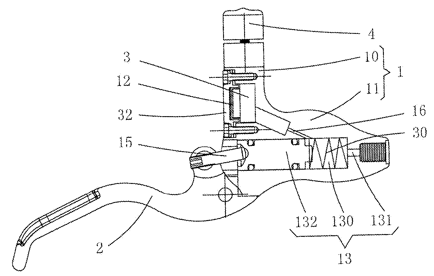
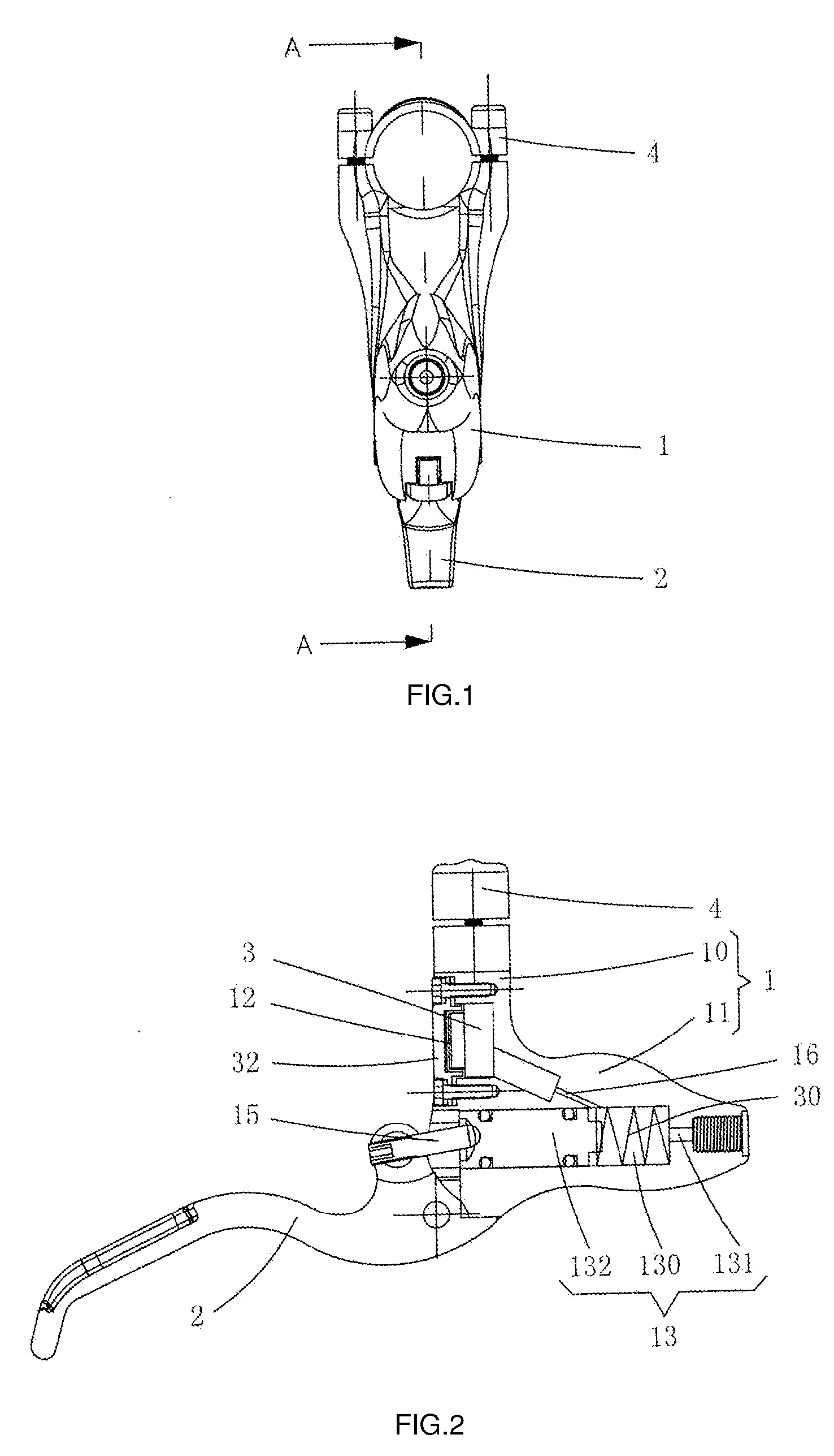
[0013]FIGS. 1 and 2 illustrate a hydraulic brake level in accordance with one embodiment. The hydraulic brake level is described in the following in connection with a bicycle. It should be understood that, however, the hydraulic brake lever could be used with various wheeled apparatus other than bicycle. In this illustrative embodiment, the hydraulic brake level generally includes a brake level base 1, a handle 2, an oil reservoir 3 and a half cover 4.

[0014]The brake level base 1 has a shape of figure “7” and includes a connecting portion 10 and a main portion 11 located at a bottom end of the connecting portion 10. The connecting portion 10 has a semicircular recessed surface at a top end of the connecting portion 10. The semicircular recessed surface cooperates with the half cover 4 to mount the hydraulic brake level to a bicycle handlebar. A cavity 12 is formed in a side of the connecting portion 10 adjacent the handle 2. The main portion 11 includes therein a brake lever cylinde...


PUM


Abstract

A hydraulic brake lever generally includes a brake lever base, a handle hinged to the brake lever base, an oil reservoir and a half cover. The brake lever base may include a connecting portion and a main portion. A top of the connecting portion may be cooperable with the half cover to mount the hydraulic brake lever to a handlebar. The main portion may include a brake lever cylinder. The brake lever cylinder may include a return spring biasing a piston in the brake lever cylinder. The piston may have an outer end hinged with a push rod and another end hinged with the handle. The oil reservoir may be disposed in one side of the connecting portion adjacent the handle, and fluidly coupled to the brake lever cylinder. The position of the oil reservoir may be higher than the position of the brake lever cylinder.

Description

BACKGROUND OF THE INVENTION[0001]1. Field of the Invention[0002]The present invention relates to hydraulic brake apparatus, and more particularly, to a hydraulic brake lever.[0003]2. Description of Related Art[0004]Hydraulic brakes have been widely used. For example, Chinese patent ZL 90207299.4 discloses a hydraulic brake apparatus for a bicycle, which includes a n-shaped brake bracket with a brake cylinder and a brake rubber pad mounted thereon. A brake handle base is hinged to a hinge handle. A brake handle cylinder, coupled to one end of the brake cylinder through an oil tube, is disposed in the brake handle base. The other end of the brake cylinder has a press rod. The press rod includes a press rod sleeve hinged to the brake handle. The press rod sleeve is operable to press the press rod to move a piston of the brake handle cylinder, causing the brake cylinder to move the rubber pad, such that the rubber pad is tightly engaged with an end surface of a bicycle rim to brake the ...

Claims


Application Information

Patent Timeline
Patent Type & Authority Applications(United States)
IPC IPC(8): B60T13/12
CPCB60T7/10B62L3/023B60T11/22
Inventor CHEN, CHENG WEN
Owner HSIN TECH SHENZHEN
Why Eureka
Try Eureka