Pipe/cable enclosure and method for enclosing pipes and cables

a technology of enclosure and pipe, which is applied in the direction of machine supports, other domestic objects, mechanical apparatus, etc., can solve the problems of transportation costs and the use of lightweight folding wall elements, and achieve the effects of reducing or preventing the vibration of the enclosure resting on the housing, good stability, and high strength

Inactive Publication Date: 2009-05-14
SIEMENS HEALTHCARE GMBH
View PDF11 Cites 6 Cited by
  • Summary
  • Abstract
  • Description
  • Claims
  • Application Information

AI Technical Summary

Benefits of technology

[0016]In another embodiment, meeting wall element edges are connected by using one or a combination of the following fastening means: snap buttons, hook-and-loop fasteners, retaining clips, hooks and eyes, guide aids. Said fastening means can be attached directly to the edges, for example, but can also be attached to legs formed at the edges, or to the outer or inner sides of the wall element in the vicinity of the edges. Snap button and hook-and-loop fasteners are preferably attached to legs formed at wall element edges. The abovementioned fastening means have the advantage of enabling the pipe / cable enclosure to be repeatedly installed and dismantled in an easy manner.
[0017]The pipe / cable enclosure is preferably implemented such that it can be inserted into a molded shape formed on a housing of the medical diagnostic device. Such a shape can be e.g. an all-round notch, a depression over the area bounded by the enclosure, an all-round raised part, a combination of these or similar. For example, the shape can also comprise a plurality of depressions at predetermined locations in the housing, into which the corresponding projections of the enclosure can be inserted. A wall element can, for example, have one or more projections on two or more sides, and these projections are inserted into corresponding depressions in the housing of the medical diagnostic device. Equally, however, the lower edge of the wall element can be flat and have no projections, and be inserted into cutouts made in raised parts on the housing of the medical diagnostic device. Insertion of the enclosure into such a shape has the advantage that the position of the enclosure on the housing of the medical diagnostic device is fixed and the enclosure is structurally stabilized, e.g. against shear deformation parallel to a lateral surface.
[0018]According to another embodiment, at least one securing element is provided in an area of the wall element facing the medical diagnostic device, and a cutout is provided on a housing of the medical diagnostic device, said securing element engaging in said cutout in the assembled state of the enclosure. The cutout can be, for example, the cutout that must be provided in the housing for the pipe and cables passing through the housing. Other cutouts can also be provided which are used exclusively for insertion of the securing element. For example, in the vicinity of the lower edge of the wall element, i.e. the edge facing the housing, springs, latching elements or similar can be attached which engage in corresponding cutouts on the housing. The securing element can also be embodied as a single piece with the wall element, e.g. implemented as a hook-shaped molded part of the edge of the wall element facing the housing. Such securing elements provide additional securing of the position of the enclosure, and vibrations of the enclosure resting on the housing can also be reduced or prevented. For example, securing elements can be provided at four different positions around the wall element, but an all-round securing element is also conceivable.
[0019]According to another aspect of the invention, a housing of a medical diagnostic device is provided which comprises pipes and cables extending from a region of the medical diagnostic device to a partition wall, the housing having around this region at least one molded shape which is embodied such that it accommodates an enclosure as claimed in one of claims 1 to 13. The at least one shape preferably includes recesses and / or raised parts. For example, the housing can have a plurality of recesses into which projections formed on a wall element can be inserted, an all-round recess into which the edge of the enclosure near the housing can be inserted, or a planar recess which extends over the length and breadth of the enclosure and is therefore able to accommodate the entire enclosure, the latter being retained in the recess e.g. by a kind of press fit. Alternatively, the housing can have raised parts on the inside and outside of a side of the wall element, the wall element being retained between these raised parts. Equally, however, the enclosure may have only raised parts which abut the outside of the circumferential wall element, the wall element again being held in a kind of press fit between these raised parts. The raised parts can be separate parts which are fastened to the housing during production or retrofit. However, the at least one shape is preferably made of a piece with the housing, thereby obviating the need for an additional assembly step during production of the housing. This also gives the housing very high strength which provides the housing with good stability with the aid of the shapes. The housing provided with shapes is particularly suitable for accommodating one of the above-described pipe / cable enclosures, since the latter can be flexibly folded and therefore matched to existing shapes in the housing. The pipe / cable enclosure is endowed with additional stability by the housing shaped in this way and shifting of the enclosure is prevented.
[0020]A method for enclosing pipework / cabling of a medical diagnostic device is also provided, wherein the pipes and cables run from the diagnostic device to a partition wall, the method comprising the following steps: providing at least one wall element with folds; cutting the wall element to a width essentially corresponding to a gap between a housing of the medical diagnostic device and the partition wall; folding the wall element around the pipes and cables at the predetermined folds, and connecting ends of the at least one wall element by means of at least one fixing element so as to form the enclosure surrounding the pipes and cables. Folding also includes simple bending or kinking, which is easily possible e.g. in the case of polypropylene hollow board. Therefore if, for example, two wall elements are used, the wall element ends which meet when the wall elements are folded around the pipes and cables are joined together by means of fixing elements. A fixing element can include, for example, an above-described molding or fastening means such as snap buttons, hook-and-loop fasteners, retaining clips or similar. In addition, the wall element is preferably inserted in at least one molded shape on the housing, the shape being implemented such that it at least partially accommodates an edge of the at least one wall element close to the housing. The cut size of the wall element is adapted accordingly in this case so that the wall element again extends from the housing to the partition wall even when it is inserted in shapes in the form of deeper recesses. The method described here enables an enclosure to be speedily installed around pipes and cables with little effort and at low cost and therefore advantageously. The method is also adaptable and also enables pipes and cables running across varying gaps between the housing of the medical diagnostic device and the partition wall to be enclosed. Moreover, the method described enables fixing of the enclosure to the partition wall to be dispensed with, which means that the constitution of the partition wall is immaterial and the method can be used in a multiplicity of environments.

Problems solved by technology

The use of a lightweight folding wall element also saves transportation costs.

Method used


Image

  • Pipe/cable enclosure and method for enclosing pipes and cables
  • Pipe/cable enclosure and method for enclosing pipes and cables
  • Pipe/cable enclosure and method for enclosing pipes and cables

Examples


Embodiment Construction

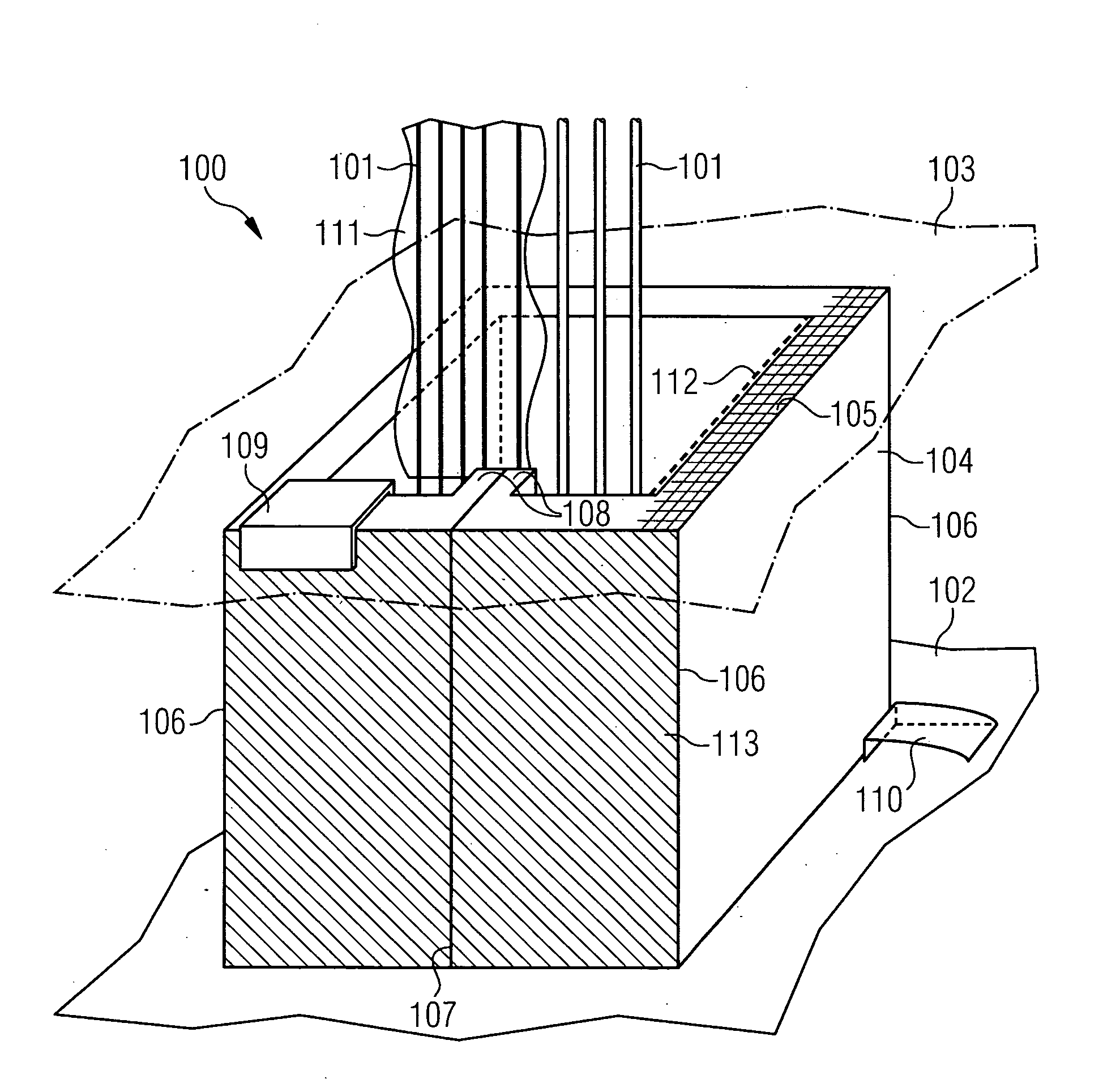
[0026]FIG. 1 is a schematic drawing of an exemplary pipe / cable enclosure 100. Pipes and cables 101 run between a housing 102 of a medical diagnostic device and a ceiling 103 of a room in which the medical diagnostic device is installed. The pipe / cable enclosure 100 comprises a wall element 104 made from a lightweight material and has an internal honeycomb structure 105 which structurally strengthens the wall element. The wall element 104 preferably comprises corrugated paperboard, the ridges of an internal fluted structure running essentially perpendicular to the housing 102. The corrugated board is, for example, 5-ply with two outer and one inner flat layer and two intermediate fluted layers, with a thickness of 5-6 mm. The corrugated board is pre-treated, e.g. impregnated with synthetic resin, to increase the moisture resistance of the corrugated board. The pipes and cables 101 can include pipes transporting compressed gaseous helium for cooling, which can cause corresponding cond...


PUM


Abstract

The invention relates to a pipe/cable enclosure for pipes and cables of a medical diagnostic device, said enclosure surrounding the pipes/cables running from the diagnostic device to a partition wall and having at least one folding wall element with folds which, in the assembled state, is disposed folded at the folds around the pipes/cables, thus surrounding the pipes/cables.

Description

CROSS REFERENCE TO RELATED APPLICATIONS[0001]This application claims priority of German application No. 10 2007 053 562.9 filed Nov. 9, 2007, which is incorporated by reference herein in its entirety.FIELD OF THE INVENTION[0002]The present invention relates to a pipe / cable enclosure for pipes and cables of a medical diagnostics device and to a method for enclosing pipes and cables.BACKGROUND OF THE INVENTION[0003]Medical diagnostic devices require incoming and outgoing pipes and cables, e.g. for energy supply. In the case of a magnetic resonance system, pipes and cables emerge from the device housing in an upper section of the device and run, for example, to the ceiling of a cage surrounding the magnetic resonance system, pass through the ceiling and are routed away out of sight of the user. In the area between the housing and ceiling the pipes and cables are visible to a system user such as a doctor or patient. To conceal and protect the pipes and cables, but also to remove the hea...

Claims


Application Information

Patent Timeline
Patent Type & Authority Applications(United States)
IPC IPC(8): F16L3/08
CPCH02G3/0487H02G3/0608H02G3/0493
Inventor DISTLER, PETERHUDAK, TIHOMIRMACIEJEWSKI, BERND
Owner SIEMENS HEALTHCARE GMBH
Why Eureka
Try Eureka