Method for making flaskless upper and lower molds, an apparatus therefor, and a method for placing a core

Active Publication Date: 2009-05-14
SINTOKOGIO LTD
View PDF8 Cites 2 Cited by
  • Summary
  • Abstract
  • Description
  • Claims
  • Application Information

AI Technical Summary

Benefits of technology

[0030]As is clear from the above, the methods of claims 1 and 8 comprise the step of putting a pair of cope and drag flasks and the match-plate in a vertical position, thereby moving the sand filling ports to an upper position, while defining upper and lower molding spaces by inserting upper and lower squeeze-plates to the respective openings of the pair of cope and drag flasks which openings are opposed to the match-plate, and the step of spraying a release agent to the two molding spaces in an upper and lower positions which spaces are defined by inserting the upper and lower squeeze-plates to the openings. Thus, the release agent can be sprayed at the time or after the molding spaces are defined and before the match-plate is moved to a vertical position, and then, after the release agent is dried, the molding sand can be supplied to the spaces. Accordingly, the

Problems solved by technology

However, the conventional molding machine to mold flaskless upper and lower molds has a problem such as insufficient molding efficiency.
Especially, a release agent is sprayed in a closed space at the final stage, and the concern has been that the release ag

Method used


Image

  • Method for making flaskless upper and lower molds, an apparatus therefor, and a method for placing a core
  • Method for making flaskless upper and lower molds, an apparatus therefor, and a method for placing a core
  • Method for making flaskless upper and lower molds, an apparatus therefor, and a method for placing a core

Examples


embodiment 1

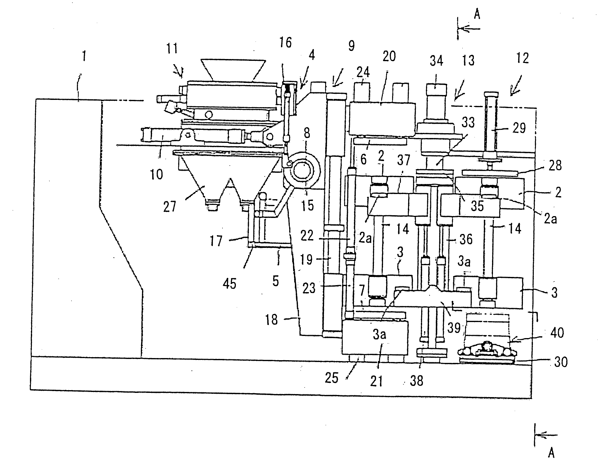
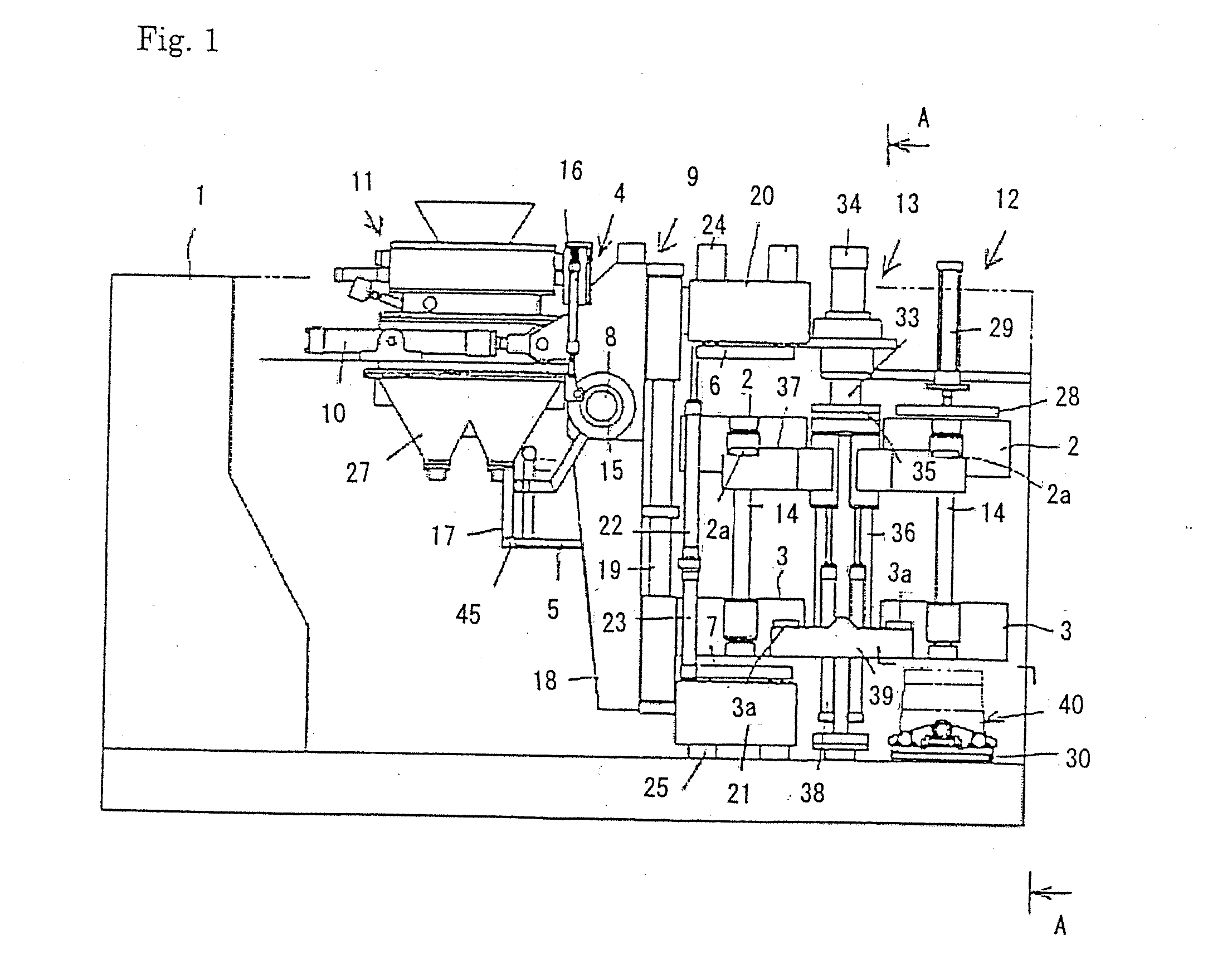
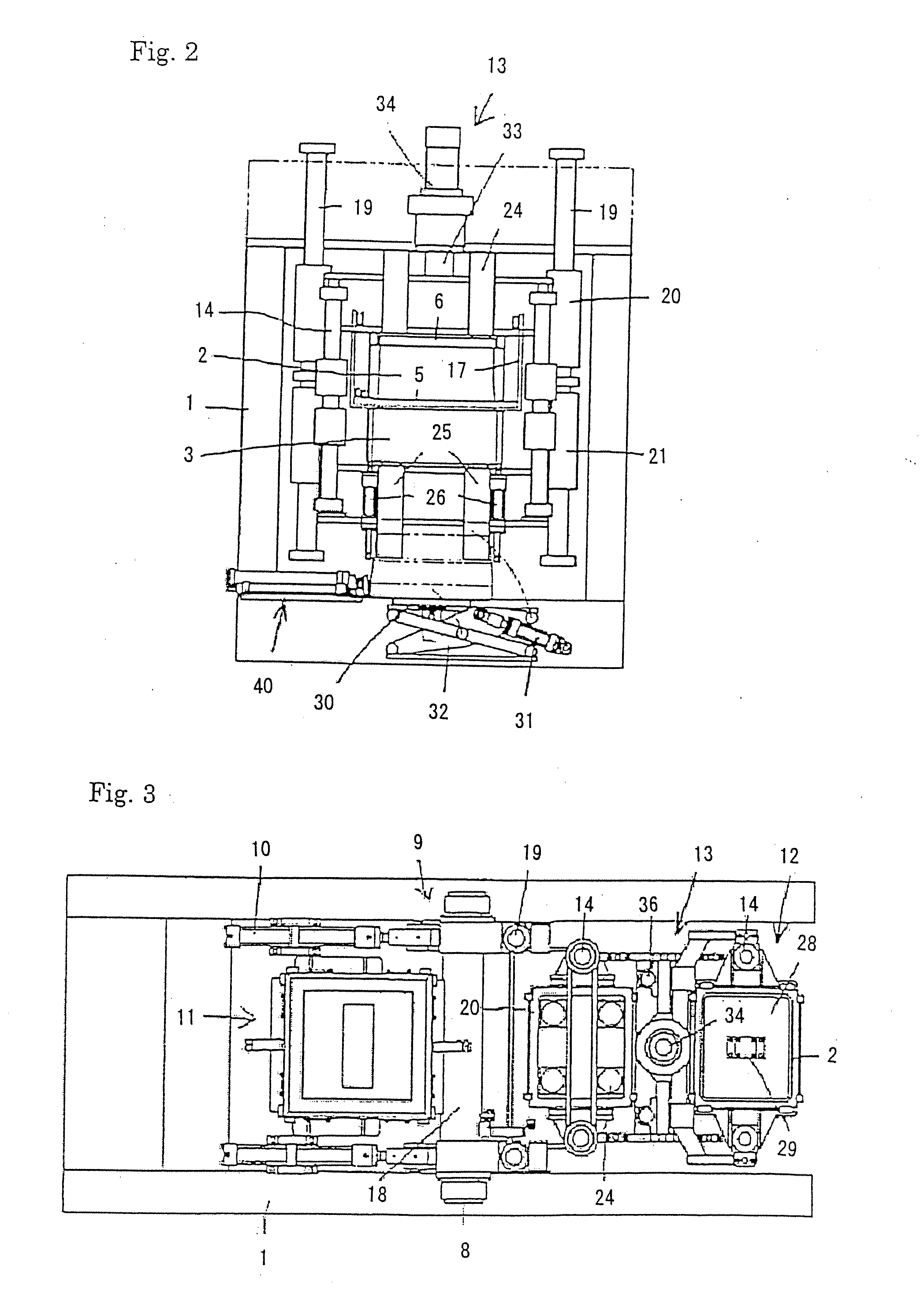
[0043]Now, we discuss one embodiment of a molding machine of the present invention for molding flaskless upper and lower molds, referring to FIGS. 1-4. As in FIGS. 1-3, the molding machine for making flaskless upper and lower molds comprises a rectangular main frame 1 that has vacant spaces in it, two pairs of cope and drag flasks 2, 3, 2, 3, match-plate 5, a squeezing mechanism 9 for squeezing molding sand, a cylinder 10, a spraying mechanisms for spraying a release agent, a sand-supplying mechanism 11, a stripping mechanism 12 for stripping molds, and a swiveling mechanism 13 for swiveling molding flasks. Each flask of the two pairs of cope and drag flasks 2, 3, 2, 3 has a sand-filling port for supplying molding sand at its side wall. The match-plate 5 is arranged so as to be able to be inserted in and withdrawn from between one of two pairs of cope and drag molding flasks by a conveying mechanism 4 for insertion and withdrawal. The squeezing mechanism 9 holds the match-plate 5 be...

embodiment 2

[0061]Now, we discuss another embodiment of the molding machine of the present invention for making flaskless upper and lower molds, referring to FIGS. 5-7. As in FIGS. 5-7, the molding machine for molding flaskless molds comprises the main frame 101 that has vacant spaces in it, a unit of a cope and drag flasks 127, match-plate 105, a squeezing mechanism 109 for squeezing molding sand, two cylinders 110, a release agent spraying mechanisms, and a sand-supplying mechanism 111. The unit of cope and drag flasks 127 is constructed such that the upper molding flask 102 is connected with the lower one 103 by a pair of connecting rods 118, 118 such that they can freely move forward and away from each other. The match-plate 5 is arranged so as to be able to be inserted in and withdrawn from the gap between the cope and drag flasks 102, 103 by a conveying mechanism 104 for insertion and withdrawal. The squeezing mechanism 109 has a unit of cope and drag flasks 127 so as to be freely attache...


PUM

PropertyMeasurementUnit
Moldableaaaaaaaaaa

Abstract

The purpose of the present invention is to provide a method to efficiently make flaskless upper and lower molds, to efficiently spray a release agent in a closed space, and to promptly place a core.
The invention is a method for making flaskless upper and lower molds that are stacked, comprises the steps of holding a match-plate between one pair of cope and drag flasks that are horizontally positioned, each of them having an sand-filling port for supplying molding sand at its side wall, defining upper and lower molding spaces by inserting upper and lower squeeze-plates to the respective openings of the pair of cope and drag flasks which openings are opposed to the match-plate, putting the pair of cope and drag flasks and the match-plate in a vertical position, and causing the sand-filling port to be placed in upper position, spraying a release agent to the two molding spaces in upper and lower positions which spaces are defined by inserting the upper and lower squeeze-plates to the open ends, supplying molding sand through the sand-filling port to the two upper and lower molding spaces, and squeezing the molding sand in the two upper and lower molding spaces.

Description

TECHNICAL FIELD[0001]The present invention relates to an appropriate method for making flaskless upper and lower molds placed one above the other, an apparatus therefor, and a method for placing a core.BACKGROUND OF THE INVENTION[0002]Molding machines that make flaskless upper and lower molds are publicly known. It comprises a compressing station and a stripping station. The compressing station is placed above a base and squeezes molding sand in a direction that is horizontal and parallel to the surface of the base floor. The pulling out station is placed near the base floor and matches upper and lower molds and strips molding flasks in a direction vertical to the surface of the floor. The machine gets two pairs of cope and drag flasks to intermittently and alternately reciprocate between the compressing station and the stripping station so as to make flaskless upper and lower molds.[0003]However, the conventional molding machine to mold flaskless upper and lower molds has a problem...

Claims


Application Information

Patent Timeline
IPC IPC(8): B29C33/58B28B7/38
CPCB22C9/108B22C11/10B22C23/02B22C17/12B22C15/02B22C11/04B22C13/12B22C17/00B22C23/00
Inventor HIRATA, MINORU
Owner SINTOKOGIO LTD
Why Eureka
Try Eureka