
Oscillating-Wing Power Generator with Flow-Induced Pitch-Plunge Phasing

Inactive Publication Date: 2009-05-14
PLATZER MAXIMILIAN F +1
View PDF6 Cites 15 Cited by
  • Summary
  • Abstract
  • Description
  • Claims
  • Application Information

AI Technical Summary

Benefits of technology

[0017]A further advantage of the proposed configuration accrues for operation as a hydropower generator because the only part exposed to the water flow is the wing. All other parts, in particular the swing arm or the guide rai

Problems solved by technology

The phenomenon of wing flutter is well known to aeronautical engineers, whereby an aircraft wing may experience catastrophic failure in a few seconds due to the fact that the wing may absorb energy from the air flow.
These prior art oscillating-wing power generators have the disadvantage of requiring a rather elaborate mechanism to enforce the wing's pitch-plunge motion at the proper phase angle between the pitch and plunge motions.

Method used


Image

  • Oscillating-Wing Power Generator with Flow-Induced Pitch-Plunge Phasing
  • Oscillating-Wing Power Generator with Flow-Induced Pitch-Plunge Phasing
  • Oscillating-Wing Power Generator with Flow-Induced Pitch-Plunge Phasing

Examples


Embodiment Construction

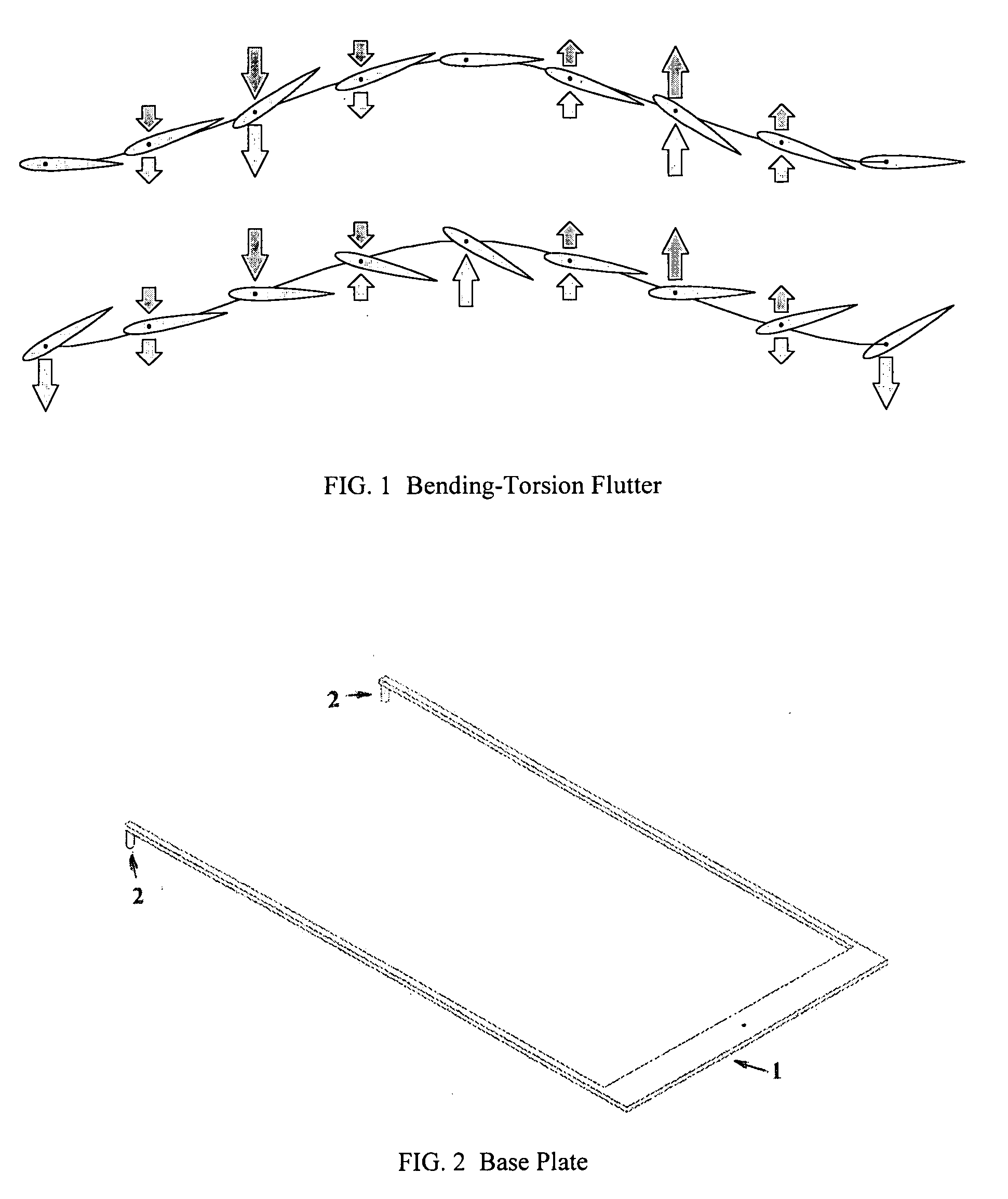
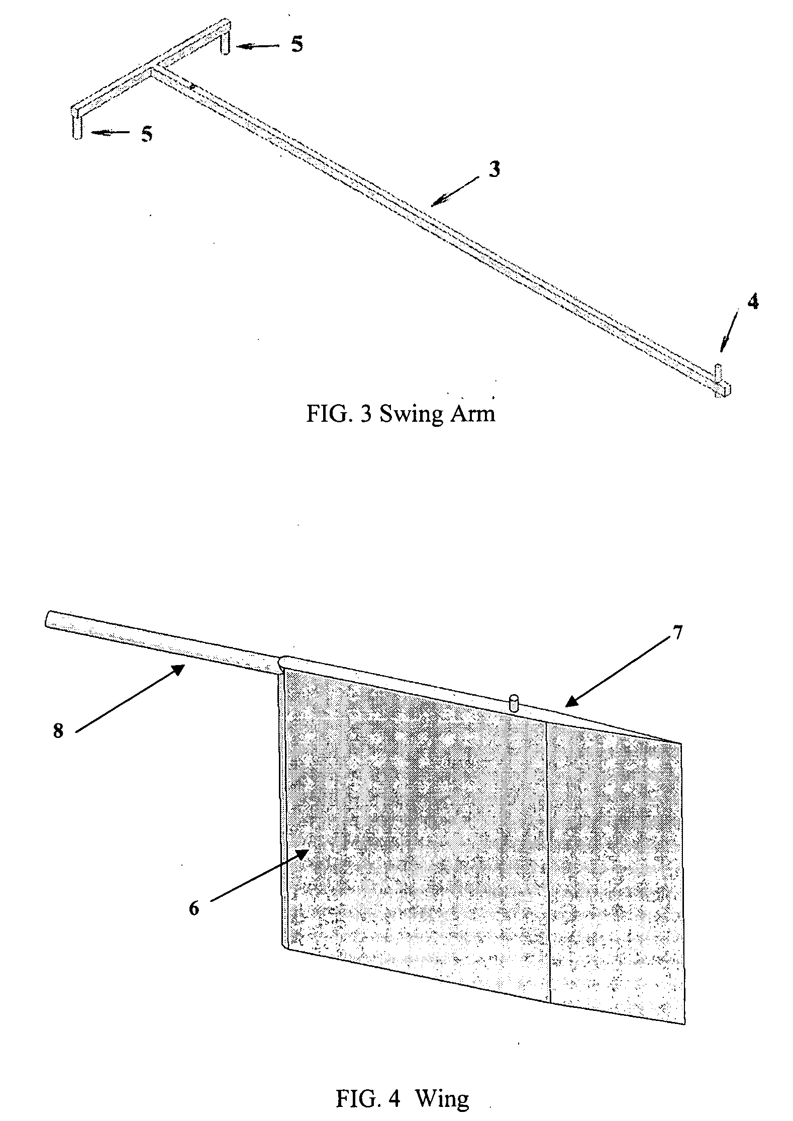
[0023]The essence of the proposed new power generator can be understood from FIGS. 5 and 6. The generator consists of the following parts: the base plate with the two support arms 1 and the two switching rods 2, the swing arm 3 with the axle 4 and the two pitch control rods 5, the wing 6 with the pitch axle 7 and the spike 8.

[0024]The principle of operation is as follows: The swing arm 3 oscillates about a vertical axis, indicated by the hole on the base plate 1, with an angular amplitude which is limited by the location of the switching rods 2. At the other end of the swing arm the wing 5 is attached to the swing arm 3 by means of the axle 4 so that it can pitch about an axis perpendicular to the swing arm and the base plate. At the end of each clockwise and counterclockwise stroke the wing 6 must be rotated quickly to the proper pitch angle. Denoting a pitch angle where the wing's leading edge points to the right as positive the wing must be set at a positive pitch angle during it...


PUM


Abstract

A new method for converting the kinetic energy of wind or water flows into electric energy, comprising wings or sails which are mounted on swing arms or on guide rails in such a way that the air or water flow induces an oscillatory wing or sail motion with a phase angle between the wing's or sail's pitch and plunge motion of about ninety degrees. Stroke reversal of the oscillatory motion is initiated by a purely aerodynamic / hydrodynamic mechanism such that the air or water flow induces a pitching moment on the wing or sail which rotates the wing or sail and thereby reverses the lift acting on the wing or sail.

Description

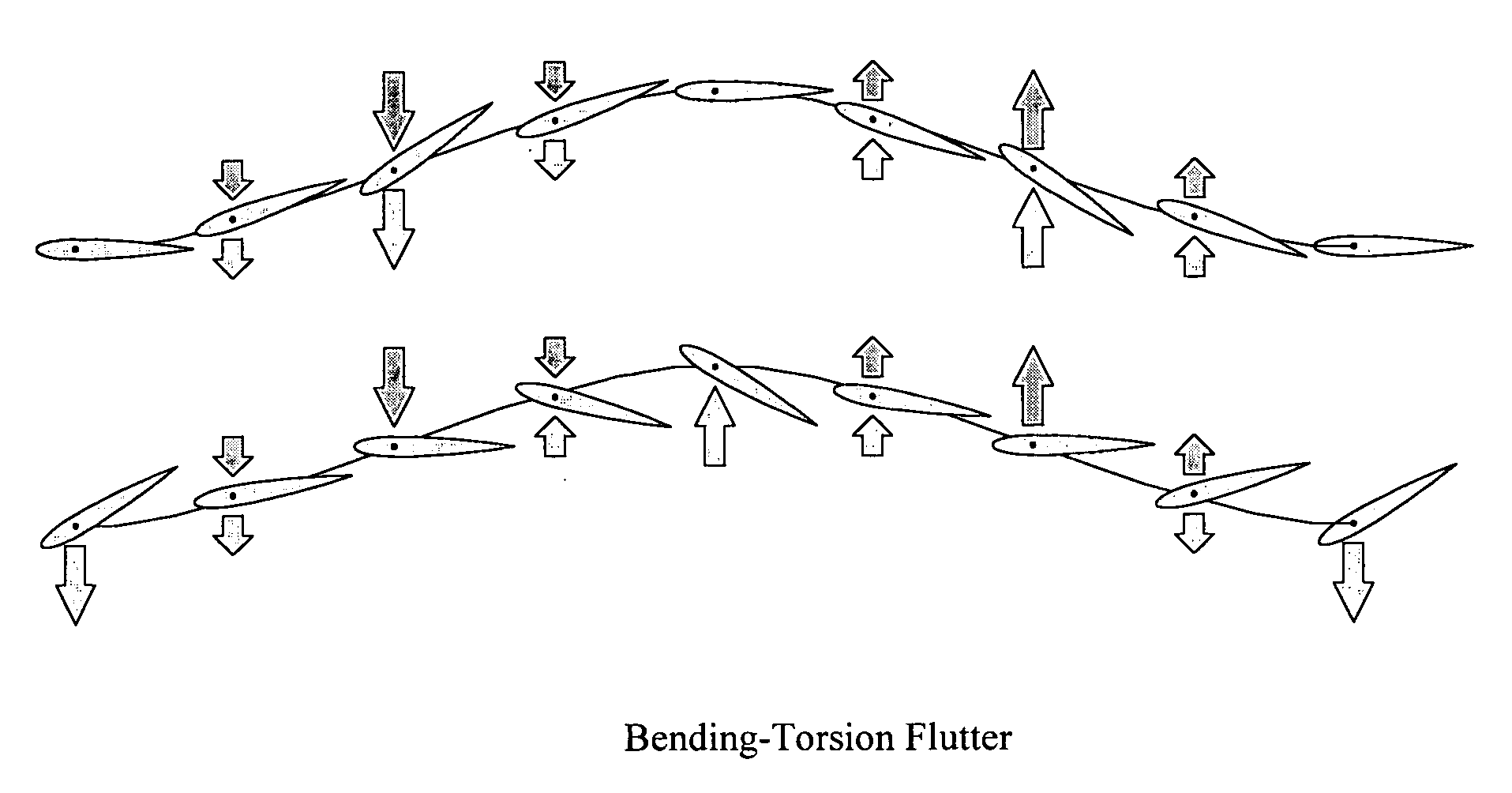
BACKGROUND OF THE INVENTION[0001]1. Field of the Invention[0002]This invention relates in general to wings and sails, and in particular to wings and sails which oscillate in such a way that they convert the energy of flowing air or water into electrical energy.[0003]2. Discussion of the Related Art[0004]The phenomenon of wing flutter is well known to aeronautical engineers, whereby an aircraft wing may experience catastrophic failure in a few seconds due to the fact that the wing may absorb energy from the air flow. This type of flutter usually requires that the wing is free to oscillate in at least two degrees of freedom, say in bending and torsion. It follows that if an airfoil is mechanically coupled in pitch and plunge it can extract energy from the flow. This is shown in FIG. 1.[0005]It is feasible to construct an oscillating wing power generator for the purpose of extracting useful power from a flow. In 1981, McKinney and DeLaurier built such a device at the University of Toro...

Claims


Application Information

Patent Timeline
IPC IPC(8): F03D9/00
CPCF03B17/00F03B17/06F03B17/065Y02E10/70F05B2260/40F05B2260/50Y02E10/28F03D5/06Y02E10/30Y02E10/20
Inventor PLATZER, MAXIMILIAN F.BRADLEY, RICHARD A.
Owner PLATZER MAXIMILIAN F
Learn More