
Method for assembling an electric motor and motor obtained using this method

Inactive Publication Date: 2009-05-14
SPAL AUTOMOTIVE
View PDF10 Cites 12 Cited by
  • Summary
  • Abstract
  • Description
  • Claims
  • Application Information

AI Technical Summary

Benefits of technology

[0014]Another aim of the present invention is to propose a method for assembling an electric motor which is simple and inexpensive to implement.

Problems solved by technology

Such motors are designed to operate in environmental situations and in positions in which they may be subject to infiltration by water and moisture, which may create electrical problems for the motor.
However, this type of assembly is not without disadvantages: in particular, when the motor is closed, that is to say when the lid and the cup-shaped part are locked relative to one another, there is no absolute guarantee that the motor will be hermetically sealed.
Despite the many efforts made to ensure this, the gasket between the two parts of the casing may not be perfectly positioned or effectively squashed to guarantee a suitable seal between the parts in contact.

Method used


Image

  • Method for assembling an electric motor and motor obtained using this method
  • Method for assembling an electric motor and motor obtained using this method
  • Method for assembling an electric motor and motor obtained using this method

Examples


Embodiment Construction

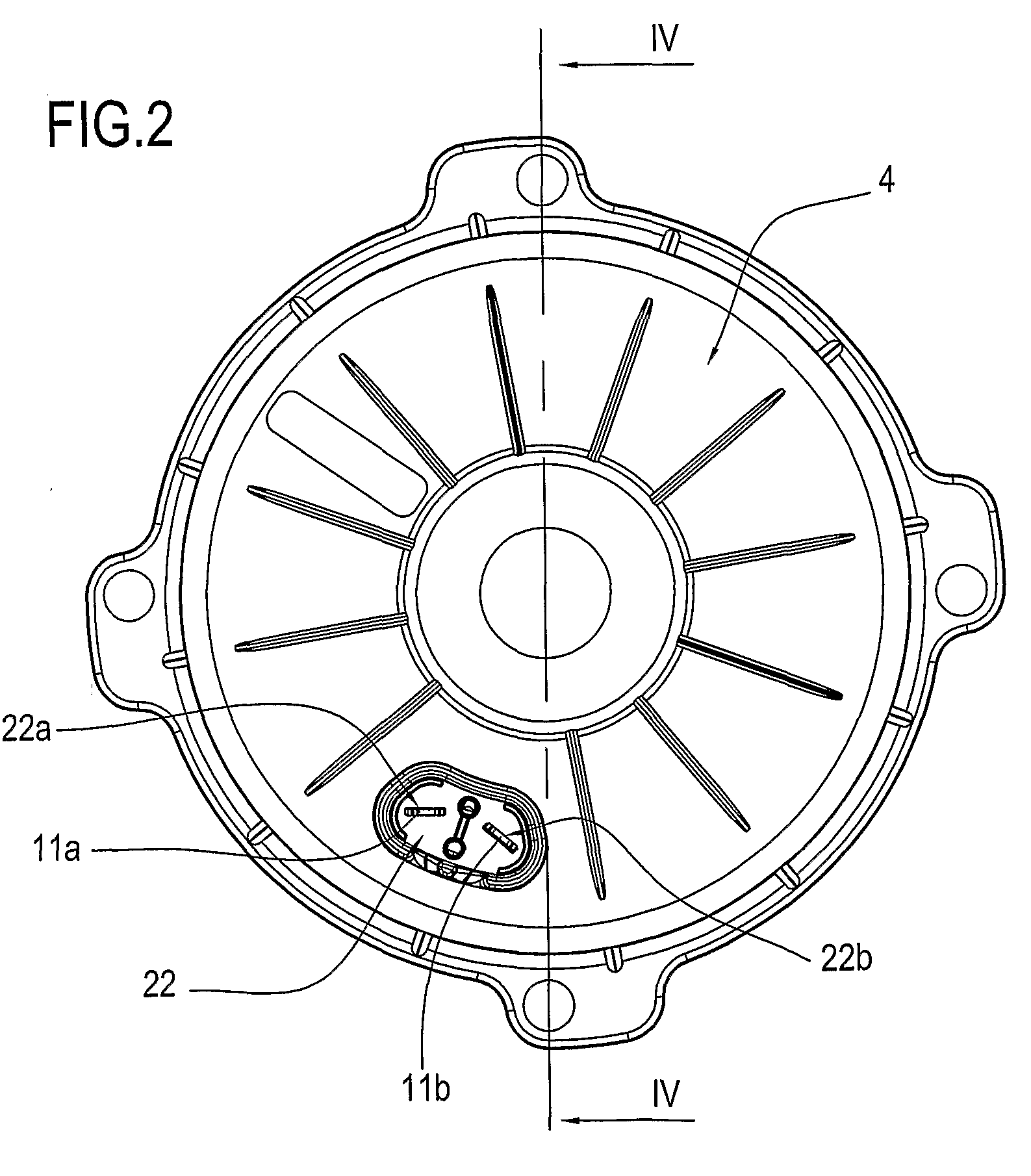
[0032]With reference to the accompanying drawings and in particular with reference to FIGS. 4 and 8, the numeral 1 denotes an electric motor assembled in accordance with the present invention.

[0033]The description below refers specifically to an electric motor, but it shall be understood that the invention may also relate to other types of rotary electric machines, for example power generators, alternators and the like.

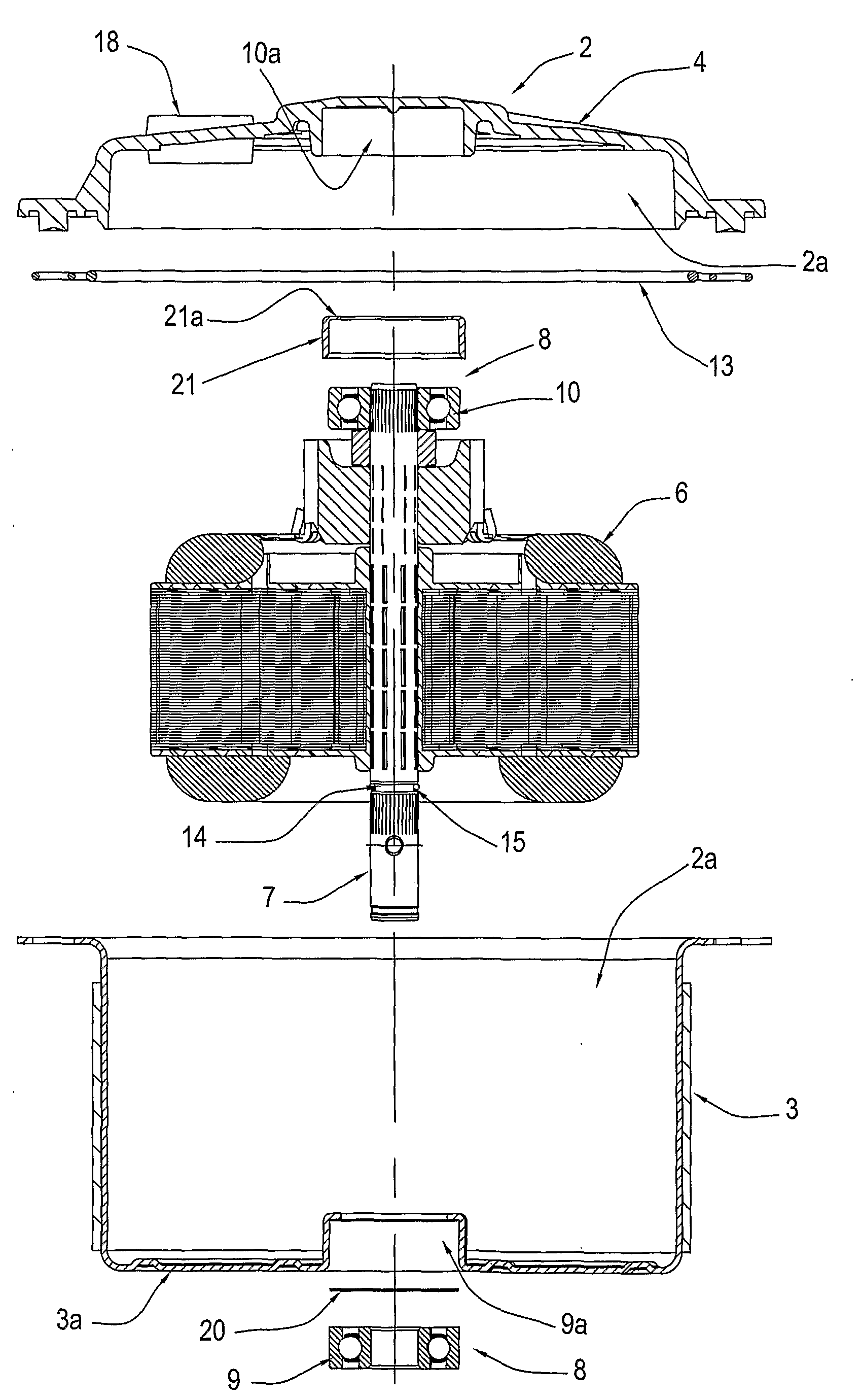
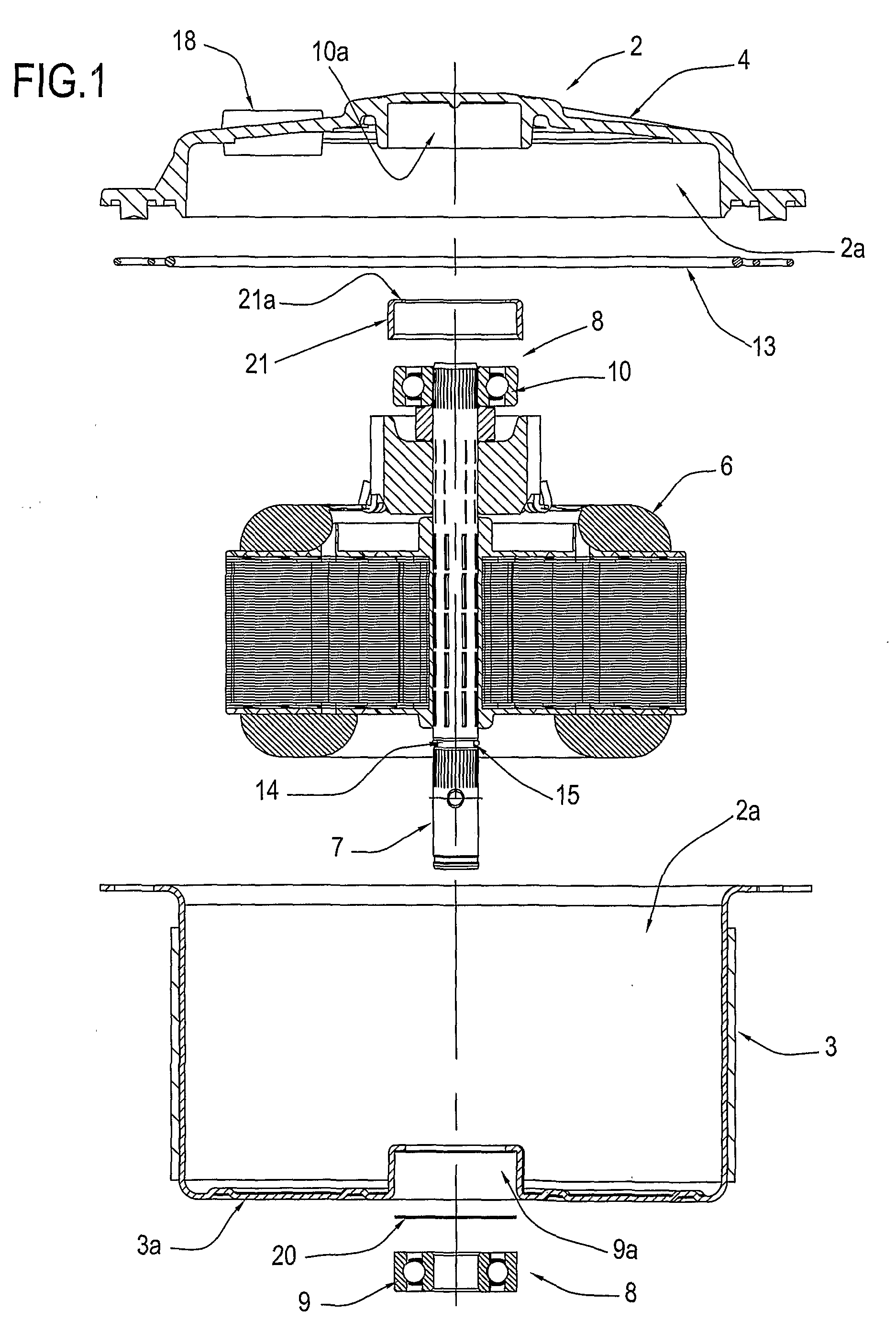
[0034]The electric motor 1 comprises, schematically, an outer casing 2 delimiting a containment compartment 2a.

[0035]The casing 2 consists of a substantially cup-shaped part or container 3 and a lid 4 connected to one another with connecting devices of the known type and therefore not illustrated in detail.

[0036]An electromagnetic unit consisting of a stator unit 5 and a rotary unit 6, of the substantially known type, is housed in the casing 2.

[0037]The rotary unit 6, able to rotate about an axis R, comprises a shaft 7 partly projecting outside the casing 2.

[0038]As ...


PUM

PropertyMeasurementUnit
Temperatureaaaaaaaaaa
Pressureaaaaaaaaaa
Poweraaaaaaaaaa

Abstract

A method for assembling an electric motor of the type comprising a stator unit (5) and a rotary unit (6) housed in a containment compartment (2a) delimited by a casing (2), comprises the step of exposing the compartment (2a) to a different pressure relative to the outside environment and the step of checking for the passage of fluid between the outside environment and the compartment (2a) in order to test the motor (1) hermetic seal.

Description

TECHNICAL FIELD[0001]The present invention relates to a method for assembling an electric motor and in particular a watertight electric motor.[0002]Specific reference is made below to an electric motor, although it shall be understood that the invention may relate to any rotary electric machine, such as an alternator or a dynamo.BACKGROUND ART[0003]In general, a rotary electric machine comprises a stator, a rotor mounted on a shaft and a casing with supports for the rotor shaft.[0004]To mount the stator and the rotor in the casing, the latter must be divided into at least two parts which can be assembled.[0005]An example of an electric machine and a method for making it is known from patent U.S. Pat. No. 5,767,596.[0006]Also known, especially in the sector of electric fans for motor vehicles, are watertight and moisture proof electric motors.[0007]Such motors are designed to operate in environmental situations and in positions in which they may be subject to infiltration by water an...

Claims


Application Information

Patent Timeline
IPC IPC(8): H02K5/00H01F7/06
CPCH02K5/10H02K5/225Y10T29/4902Y10T29/49009H02K15/14
Inventor SPAGGIARI, ALESSANDRO
Owner SPAL AUTOMOTIVE
Learn More