Electronic Device

a technology of electronic devices and color displays, applied in static indicating devices, cathode-ray tube indicators, instruments, etc., can solve the problems of ineffective color display hardware, high cost, complicated and expensive hardware, etc., and achieve the effect of reducing the burden on simplifying the configuration of the first control unit, and reducing cos

Inactive Publication Date: 2009-05-14
MURATA MASCH LTD
View PDF8 Cites 15 Cited by
  • Summary
  • Abstract
  • Description
  • Claims
  • Application Information

AI Technical Summary

Benefits of technology

[0011]when the second LCD, which is different from the first LCD, is connected to the electronic device, the second control unit communicates with the first control unit and controls the second LCD. Since the second control unit controls the second LCD, the burden on the first control unit can be reduced. Accordingly, the electronic device can be provided in which a configuration of the first control unit can be simplified, the cost can be reduced, and the LCD of various types can be used.
[0012]In one embodiment of the present invention, the second LCD is a color LCD, and the color LCD, which handles a large amount of data, can be used. Moreover, the second control unit performs complex calculation needed for color display, and therefore, the configuration of the first control unit can be simplified.
[0013]In one embodiment of the present invention, the interface is a serial interface. Since the second control unit is connected via the serial interface in which a cable can be easily thinned, the cable in the electronic device can be easily handled, and the second control unit can be arranged at a proper position, enhancing scalability. Further, since the serial interface that enables high-speed communication is used, even when the data amount handled between the first and second control units is large, the data content can be smoothly displayed on the second LCD.
[0014]In one embodiment of the present invention, by communicating with the second control unit, the first control unit acquires the contents of operations performed by an operation unit connected to the second control unit. When the operation unit is added along with the second LCD, the first control unit recognizes the contents of operations performed by the added operation unit, and properly processes the operations. Accordingly, the product lineup in which the operation unit is changed can be easily achieved.

Problems solved by technology

Therefore, the hardware used for the color display tends to be complicated and expensive.
Moreover, when the monochrome LCD is attached, the hardware for the color LCD becomes useless.

Method used


Image

  • Electronic Device
  • Electronic Device
  • Electronic Device

Examples


Embodiment Construction

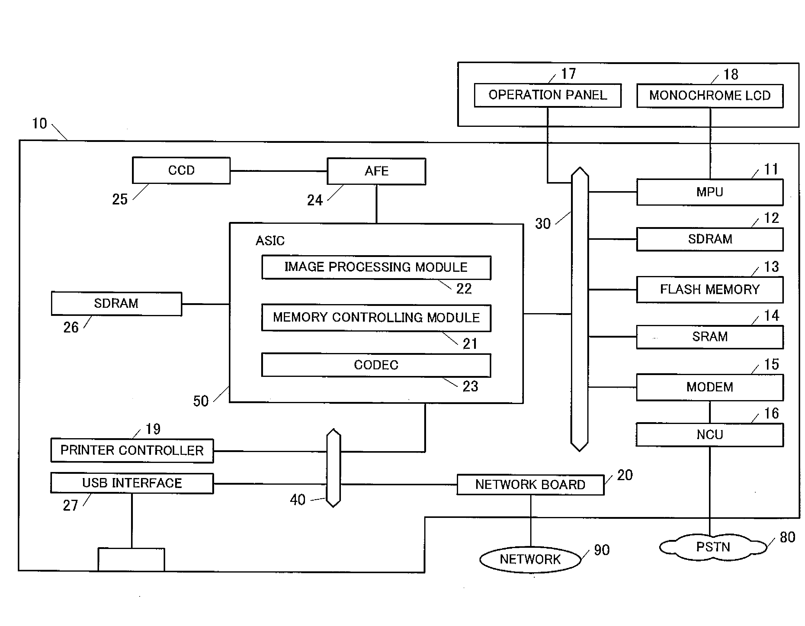
[0019]An embodiment of the present invention is now described with reference to the drawings. FIG. 1 is a block diagram of an example in which a monochrome LCD 18 is connected to an MFP 10 including a copier function and a facsimile function according to an embodiment of the present invention.

[0020]As illustrated in FIG. 1, the MFP 10 of the present embodiment includes a Micro Processing Unit (MPU) 11, a Synchronous Dynamic Random Access Memory (SDRAM) 12, and a flash memory 13. The MPU 11, the SDRAM 12, and the flash memory 13 are connected to each other via a local bus 30.

[0021]The MPU 11 is a control unit that controls the entire MFP. The MPU 11 reads and executes various programs stored in the flash memory 13, and performs functions such as a facsimile function, a scanner function, and a copier function, which are described later. The SDRAM 12 is a memory that can read and write, and is used as a working area for executing the programs.

[0022]A static RAM (SRAM) 14 and a modem 15...


PUM


Abstract

An electronic device includes first display means that displays an image in monochrome, first control means that controls the display of the monochrome image, and interface means that is used to communicate with the first control means. When second control means that controls second display means is connected to the interface means, the first control means communicates with the second control means via the interface means.

Description

CROSS-REFERENCE TO RELATED APPLICATION[0001]This application claims priority under 35 U.S.C. 119 to Japanese Patent Application No. 2007-290966, filed on Nov. 8, 2007, which application is hereby incorporated by reference in its entirety.BACKGROUND OF THE INVENTION[0002]1. Field of the Invention[0003]The present invention relates to an electronic device that includes a Liquid Crystal Display (LCD) and, more specifically, relates to an electronic device in which the type of LCD can be easily changed in accordance with the grade of a model.[0004]2. Description of the Related Art[0005]An electronic device has been conventionally known in which either a monochrome LCD or a color LCD is selected and attached. In such an electronic device including the above-described configuration, the type of LCD can be changed, and a product lineup that is widely compatible with the grade required by a user can be easily expanded. By standardizing the configuration other than the LCD and a control unit...

Claims


Application Information

Patent Timeline
Patent Type & Authority Applications(United States)
IPC IPC(8): G09G5/00
CPCG09G5/006G09G2320/0673G09G5/028
Inventor OKAMOTO, SATOSHI
Owner MURATA MASCH LTD
Why Eureka
Try Eureka