
Liquid crystal display device and driving method thereof

a technology of liquid crystal display and driving method, which is applied in the direction of semiconductor devices, instruments, optics, etc., can solve the problems of high manufacturing cost, waste of process time and manufacturing cost, etc., and achieve the effect of reducing the number of data lines

Active Publication Date: 2009-05-14
LG DISPLAY CO LTD
View PDF7 Cites 0 Cited by
  • Summary
  • Abstract
  • Description
  • Claims
  • Application Information

AI Technical Summary

Benefits of technology

[0013]Accordingly, it is an advantage of the present invention to provide a liquid crystal display device and a driving method thereof that are adaptive for reducing the number of data lines as well as the number of data drive integrated circuits corresponding thereto.
[0014]In order to achieve these and other advantages of the invention, a liquid crystal display device according to one aspect of the present invention includes a plurality of data lines; a plurality of gate lines provided in a direction crossing the data lines; first and second control lines provided in a direction being parallel to the gate lines; first liquid crystal cells provided at one side of the data lines; second liquid crystal cells provided at the other side of the data lines; a first switching part provided for each first liquid crystal cell to apply video signals supplied from the data lines to the first liquid crystal cells under control of the first control line and the gate line; and a second switching part provided for each second liquid crystal cell to apply video signals supplied from the data lines to the second liquid crystal cells under control of the second control line and the gate line.
[0015]The liquid crystal display device further includes a gate driver for sequentially applying a gate signal to the gate lines during an ½ frame interval; a data driver for applying said video signals to the data lines when said gate signal is applied to the gate lines; and a control signal supplier for supplying control signals alternated for each ½ frame unit to the first and second control lines.
[0016]In the liquid crystal display device, the first switching part includes a first thin film transistor connected to the gate line to be turned on when said gate signal is applied, thereby receiving said video signal; and a second thin film transistor turned on when said control signal is applied to the first control line to apply said video signal to the first liquid crystal cell.
[0017]In the liquid crystal display device, the second switching part includes a third thin film transistor connected to the gate line to be turned on when said gate signal is applied, thereby receiving said video signal; and a fourth thin film transistor turned on when said control signal is applied to the second control line to apply said video signal to the second liquid crystal cell.
[0018]The first and second liquid crystal cells receive said video signals alternately for each ½ frame unit in response to said control signals applied alternately for each ½ frame unit.

Problems solved by technology

Therefore, the related art LCD has a drawback in that a number of data lines DL1 to DLm should be provided to drive the liquid crystal display panel 2 and hence process time and a manufacturing cost are wasted.
Furthermore, the related art LCD has a problem in that because a large number of data drive integrated circuits (IC's) are included in the data driver 4 so as to drive the m data lines DL1 to DLm, the manufacture cost is high.

Method used


Image

  • Liquid crystal display device and driving method thereof
  • Liquid crystal display device and driving method thereof
  • Liquid crystal display device and driving method thereof

Examples


Embodiment Construction

[0033]Reference will now be made in detail to embodiments of the present invention, examples of which are illustrated in the accompanying drawings.

[0034]Hereinafter, embodiments of the present invention will be described in detail with reference to FIGS. 2 to 7.

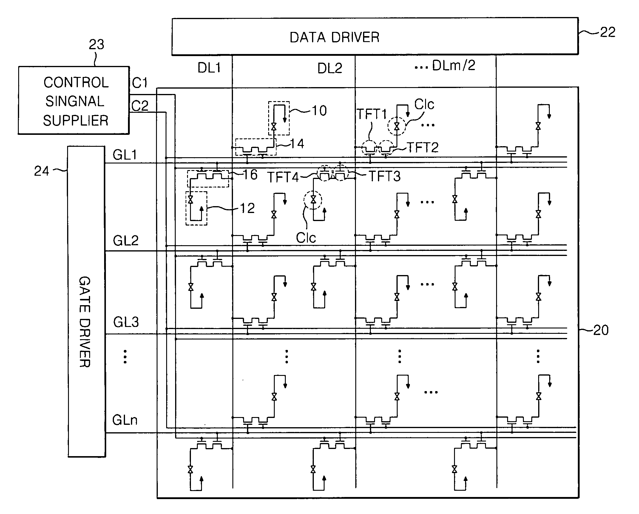
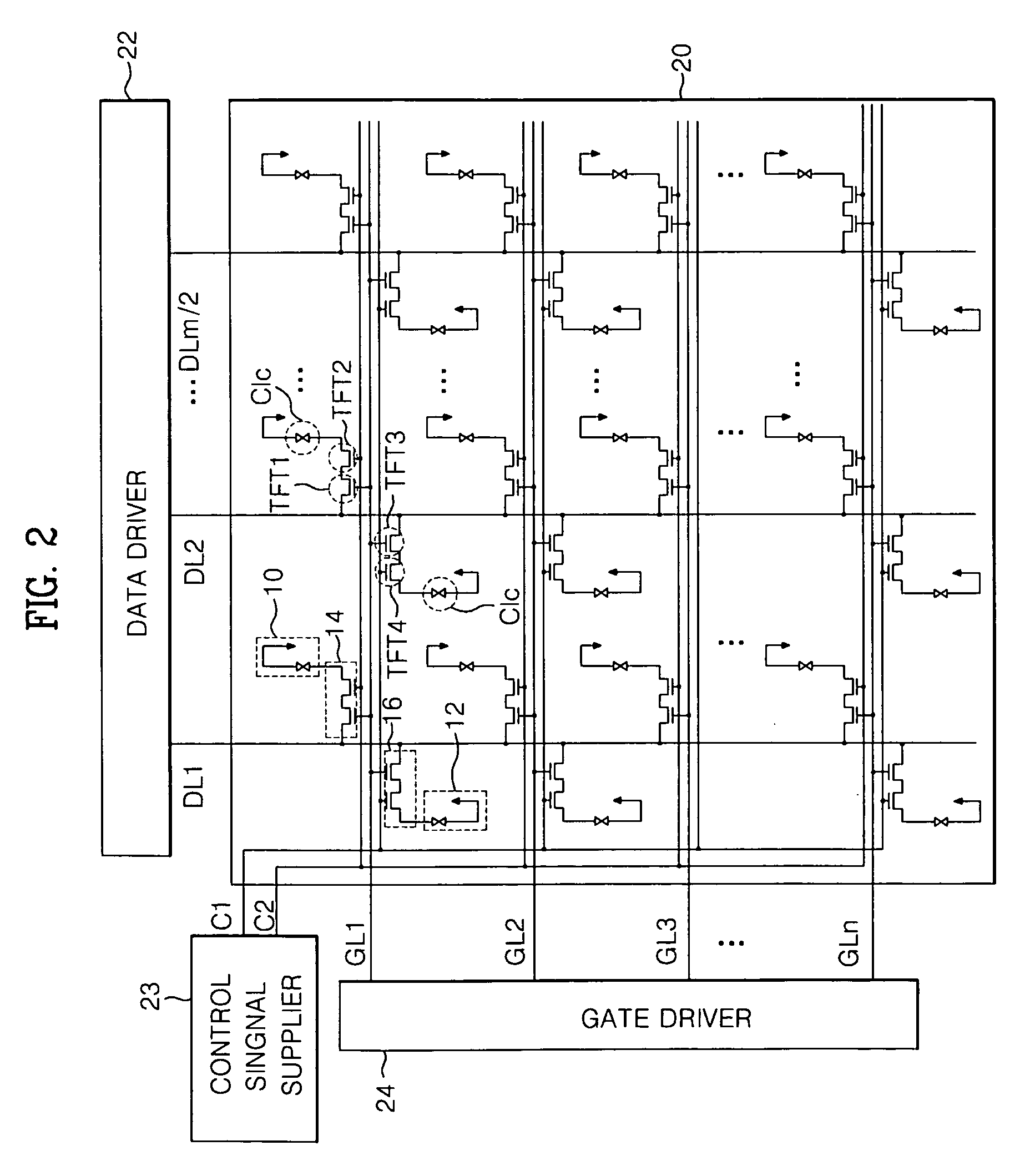
[0035]FIG. 2 schematically shows a liquid crystal display (LCD) according to a first exemplary embodiment of the present invention.

[0036]Referring to FIG. 2, the LCD according to the first embodiment of the present invention includes a liquid crystal display panel 20, a data driver 22 for driving data lines DL1 to DLm / 2 of the liquid crystal display panel 20, a gate driver 24 for driving gate lines GL1 to GLn of the liquid crystal display panel 20, and a control signal supplier 23 for supplying control signals to first and second control lines C1 and C2 provided in parallel to the gate lines GL1 to GLn.

[0037]The liquid crystal display panel 20 is comprised of first and second liquid crystal cells 10 and 12 provided alternatel...


PUM

PropertyMeasurementUnit
data voltageaaaaaaaaaa
voltageaaaaaaaaaa

Abstract

A liquid crystal display device and a driving method thereof for reducing the number of data lines and the number of data drive integrated circuits corresponding thereto are disclosed. In the device, a plurality of gate lines is provided in a direction crossing a plurality of data lines. First and second control lines are provided in a direction being parallel to the gate lines. First liquid crystal cells are provided at one side on a basis of the data lines. Second liquid crystal cells are provided at other side on a basis of the data lines. A first switching part is provided for each first liquid crystal cell to apply video signals supplied from the data lines to the first liquid crystal cells under control of the first control line and the gate line. A second switching part is provided for each second liquid crystal cell to apply video signals supplied from the data lines to the second liquid crystal cells under control of the second control line and the gate line.

Description

[0001]This application claims the benefit of Korean Patent Application No. P2003-92697 filed in Korea on Dec. 17, 2003, which is hereby incorporated by reference.BACKGROUND OF THE INVENTION[0002]1. Field of the Invention[0003]This invention relates to a liquid crystal display, and more particularly to a liquid crystal display device and a driving method thereof that are adaptive for reducing the number of data lines as well as the number of data drive integrated circuits corresponding thereto.[0004]2. Description of the Related Art[0005]Generally, a liquid crystal display (LCD) controls the light transmittance of a liquid crystal using an electric field, thereby displaying a picture. To achieve this, the LCD includes a liquid crystal display panel having a pixel matrix and a driving circuit for driving the liquid crystal display panel. The driving circuit drives the pixel matrix such that picture information can be displayed on the display panel.[0006]FIG. 1 illustrates a convention...

Claims


Application Information

Patent Timeline
Patent Type & Authority Applications(United States)
IPC IPC(8): G09G3/36G02F1/133G02F1/1362
CPCG02F1/13624G02F1/136286G09G2310/02G09G2300/0814G09G3/3659G02F1/133
Inventor KIM, WOO HYUN
Owner LG DISPLAY CO LTD
Features
  • Generate Ideas
  • Intellectual Property
  • Life Sciences
  • Materials
  • Tech Scout
  • Unparalleled Data Quality
  • Higher Quality Content
  • 60% Fewer Hallucinations
Learn More