Eureka AIR delivers breakthrough ideas for toughest innovation challenges, trusted by R&D personnel around the world.

Driving device, electro-optical device, and electronic apparatus

Inactive Publication Date: 2009-05-14
SEIKO EPSON CORP
View PDF5 Cites 14 Cited by
  • Summary
  • Abstract
  • Description
  • Claims
  • Application Information

AI Technical Summary

Benefits of technology

[0007]An advantage of some aspects of the invention is to provide a driving device and a driving method that is capable of displaying an image with high quality. In addition, the invention provides, as an advantage of some aspects thereof, an electro-optical device that is provided with such a driving device and an electro-optical device that is operated by such a driving method. Moreover, the invention further provides, as an advantage of some aspects thereof, an electronic apparatus that is provided with such an electro-optical device.

Problems solved by technology

For this reason, even though the problem of display unevenness due to a difference in brightness does not arise, which is achieved by changing the sequential order of the supply of image signals to data lines, there is an adverse possibility of the occurrence of another image problem such as the flickering of a display screen, though not limited thereto, which is attributable to a brightness level change on a display screen in accordance with the change in the sequential order of the supply of image signals.
As explained above, these techniques of the related art have a technical disadvantage in that it is difficult to achieve high display quality.
Such a brightness difference could cause display unevenness in the display area of an electro-optical device.
As a disadvantageous effect of such movement of a high brightness area portion, the flickering of a display screen, though not limited thereto, could be visually recognized in the display area of an electro-optical device.

Method used


Image

  • Driving device, electro-optical device, and electronic apparatus
  • Driving device, electro-optical device, and electronic apparatus
  • Driving device, electro-optical device, and electronic apparatus

Examples


Embodiment Construction

[0055]With reference to the accompanying drawings, exemplary embodiments of the present invention are described below.

Electro-Optical Device

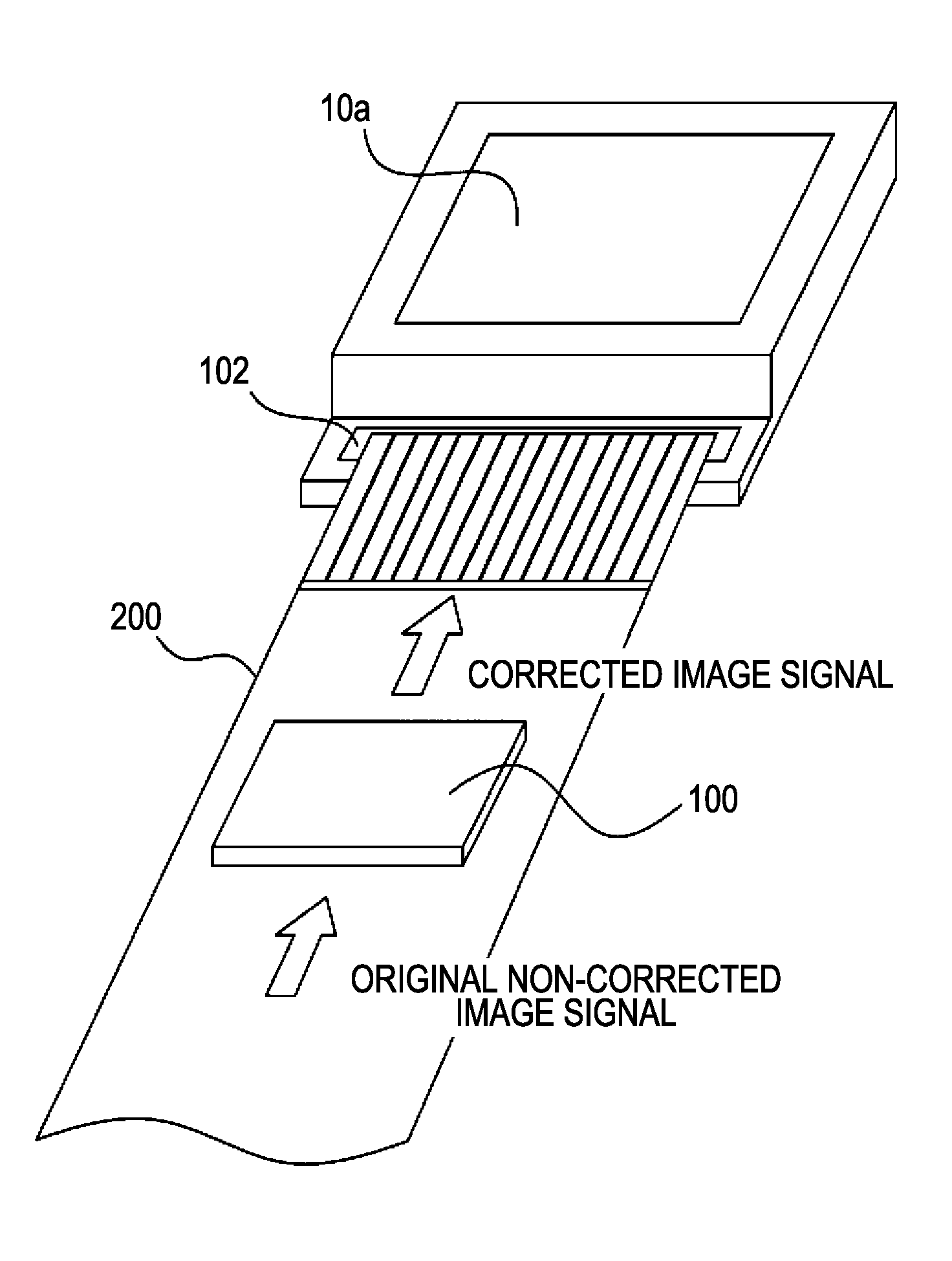
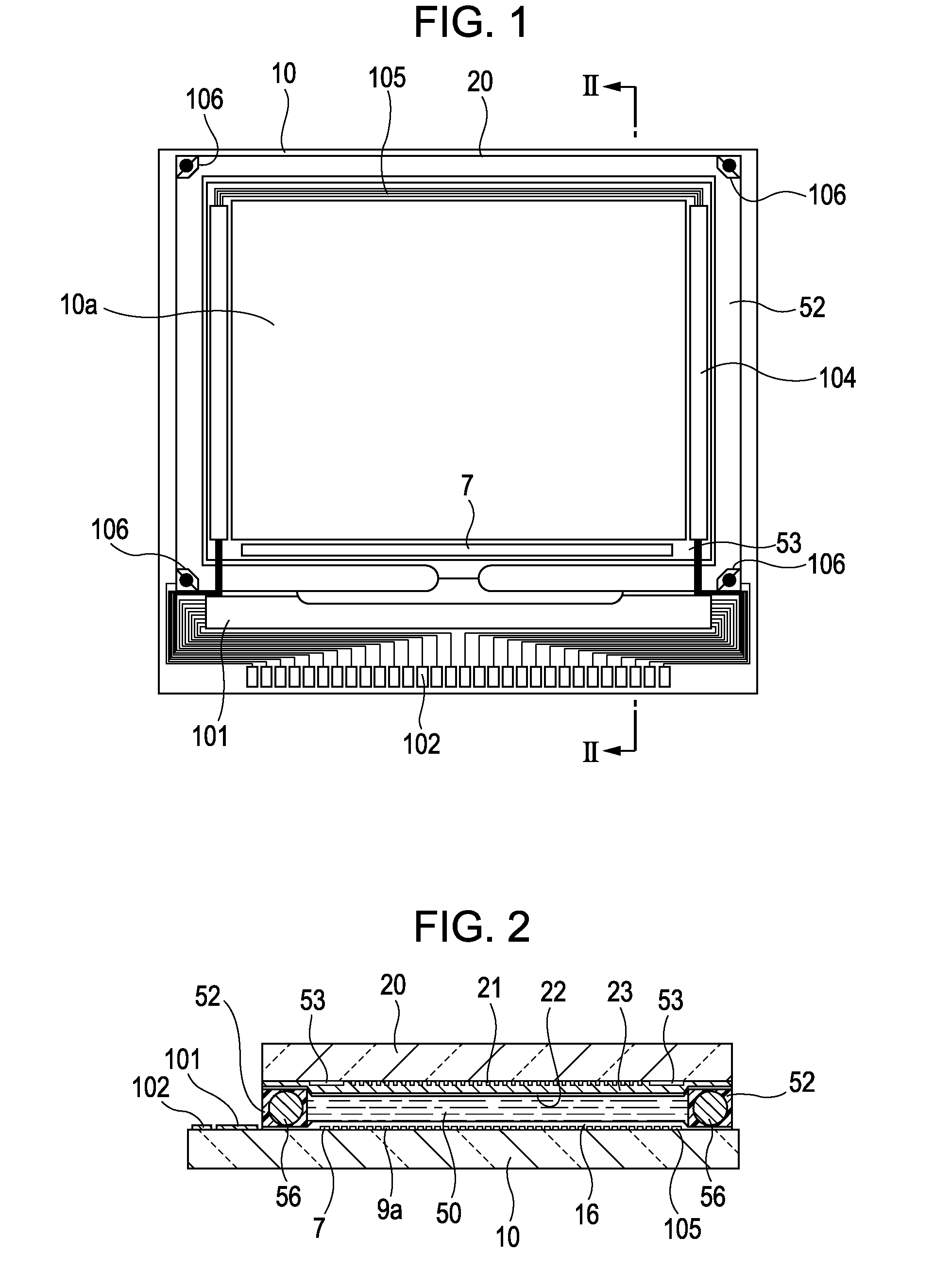
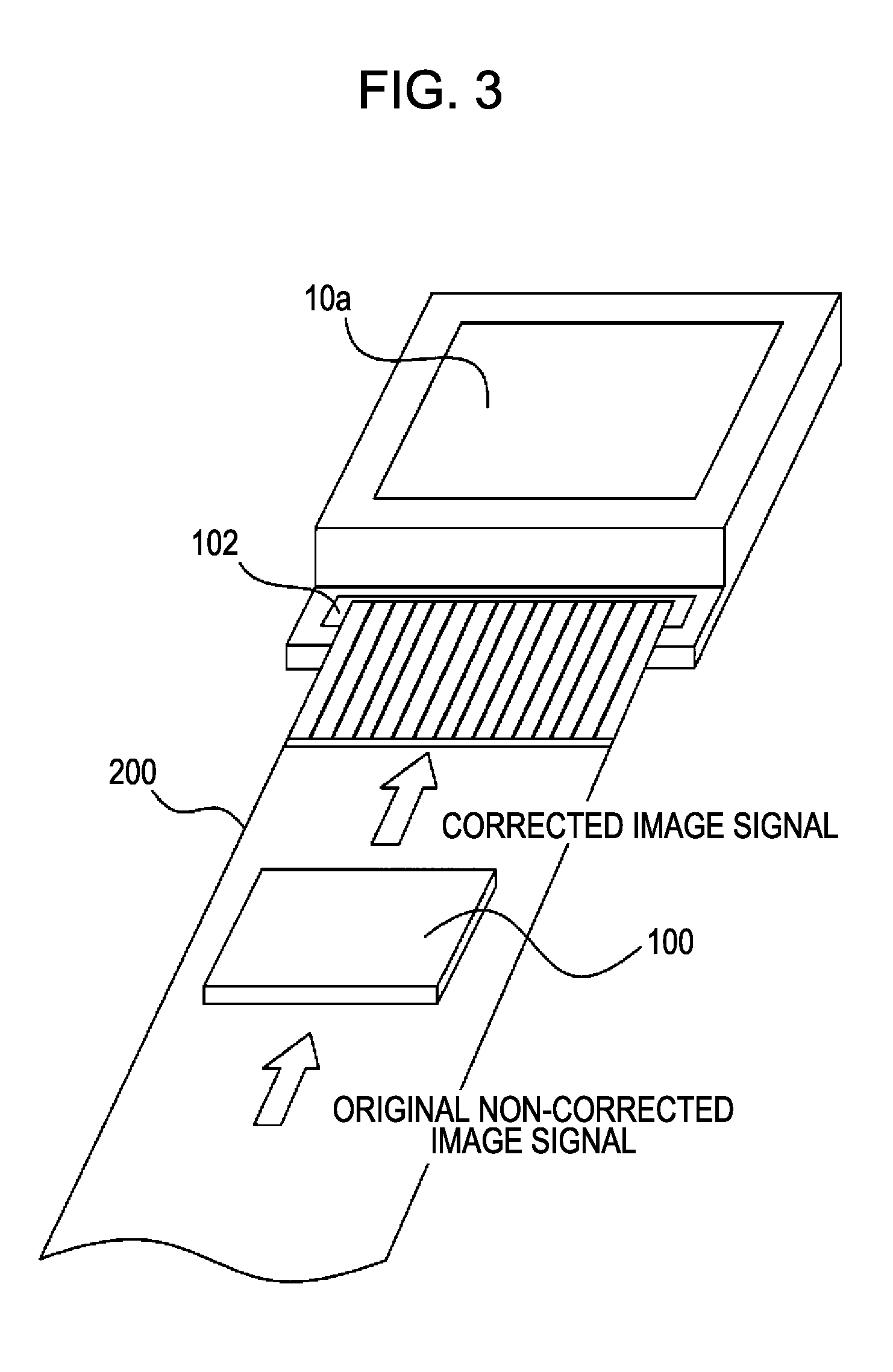
[0056]First of all, an example of the configuration of an electro-optical device that is driven by a driving device (i.e., driver) according to an exemplary embodiment of the invention is explained while referring to FIGS. 1, 2, and 3. In the following description of an exemplary embodiment of the invention, a liquid crystal device that conforms to a thin-film-transistor (hereafter abbreviated as TFT) active-matrix driving scheme is taken as an example of various kinds of electro-optical devices to which a driving device according to an aspect of the invention can be applied. It is assumed that the liquid crystal device explained below is provided with a built-in driving circuit.

[0057]With reference to FIGS. 1 and 2, an explanation is given of an example of the general configuration of an electro-optical device (e.g., liquid crystal device) acco...


PUM


Abstract

A driving device for driving an electro-optical device includes an outputting section that divides original image signal into and outputs a number of signal portions. The number corresponds to a number of groups of data lines. An assigning section assigns the signal portions to the data lines of corresponding group. A changing section determines an order that the signal portions are to be supplied to the data lines of the corresponding group and changes the order. A correcting section corrects the signal portions to reduce a difference in brightness in the display area generated by the changed order of the signal portions. A supplying section supplies the corrected signal portions to the data lines in accordance with the changed order.

Description

BACKGROUND[0001]1. Technical Field[0002]The present invention relates to a device and a method for driving an electro-optical device such as a liquid crystal device or the like. In addition, the invention relates to an electro-optical device that is provided with such a driving device and an electro-optical device that is operated by such a driving method. Moreover, the invention further relates to an electronic apparatus that is provided with such an electro-optical device. A non-limiting example of an electronic apparatus to which the invention is directed is a liquid crystal projector.[0003]2. Related Art[0004]In the technical field to which the present invention pertains, a driving device that supplies an image signal to each of a plurality of data line groups has been proposed. In the configuration of such a driving device of the related art, each of the plurality of data line groups is made up of more than one data line. For example, a technique that supplies an image signal t...

Claims


Application Information

Patent Timeline
IPC IPC(8): G06F3/038
CPCG09G3/2011G09G3/3688G09G2320/0247G09G2310/0218G09G2310/0213G09G3/36G02F1/133G09G3/20
Inventor ITO, AKIHIKO
Owner SEIKO EPSON CORP
Why Eureka
Eureka Blog
Learn More