Transflective LCD unit

a liquid crystal display and transflective technology, applied in non-linear optics, instruments, optics, etc., can solve the problems of leakage of light, inability to obtain satisfactory black color or dark state in the reflective area,

Active Publication Date: 2009-05-14
NEC LCD TECH CORP
View PDF3 Cites 7 Cited by
  • Summary
  • Abstract
  • Description
  • Claims
  • Application Information

AI Technical Summary

Benefits of technology

[0013]In view of the above, it is an object of the present invention to provide a transflective LCD unit which is capable suppressing the leakage light in the vicinity of the boundary between the reflective area and the transmissive area.

Problems solved by technology

The transflective LCD unit described in Patent Publication-1, however, has a problem in that a satisfactory black color or dark state cannot be obtained in the reflective area even if the optical axis is adjusted therein.
In the LCD unit shown in FIG. 15, there is a possibility that a leakage light occurs due to disturbance of the orientation of LC molecules in the vicinity of the boundary between the reflective area and the transmissive area during display of a dark state.

Method used


Image

  • Transflective LCD unit
  • Transflective LCD unit
  • Transflective LCD unit

Examples


first embodiment

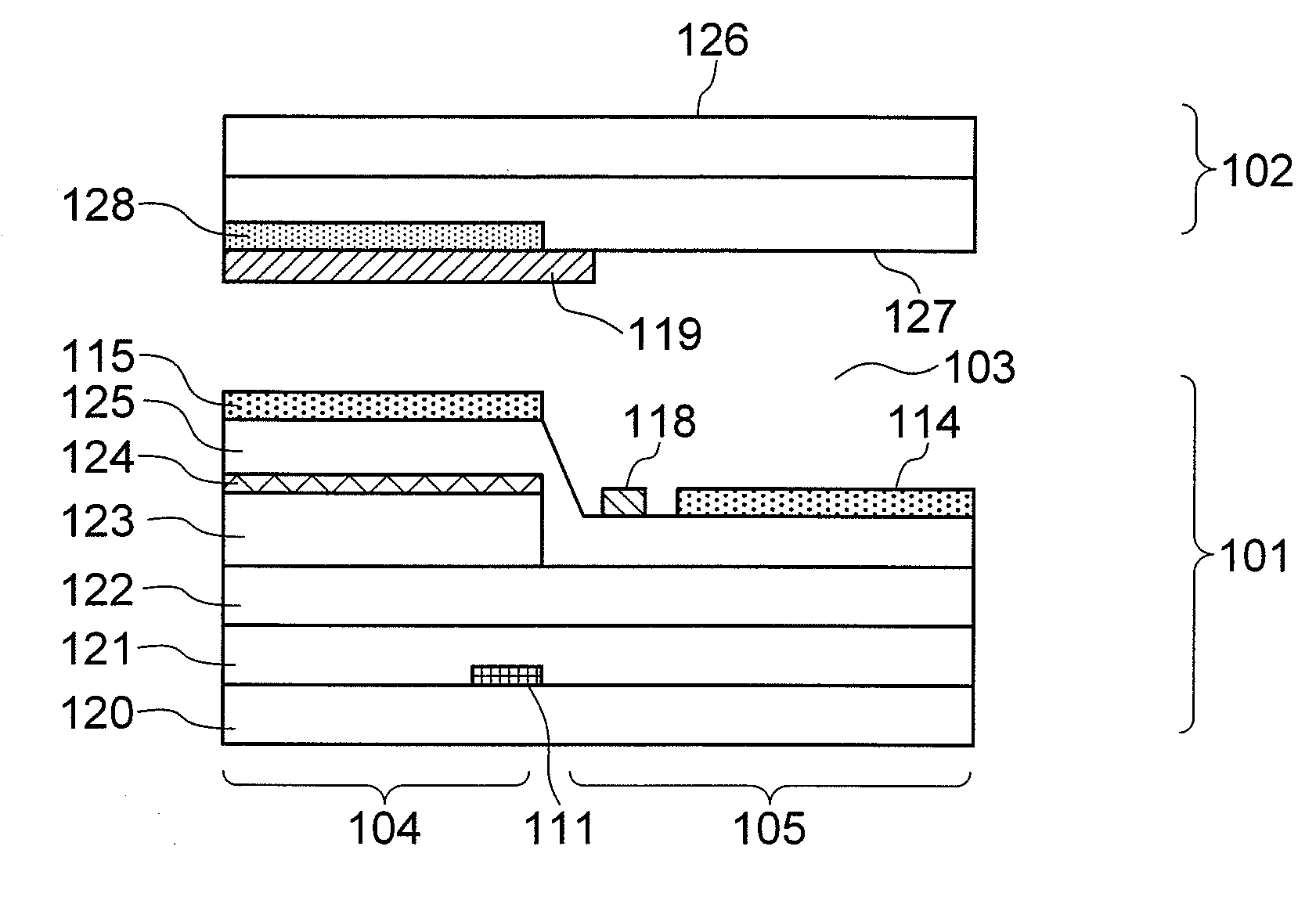
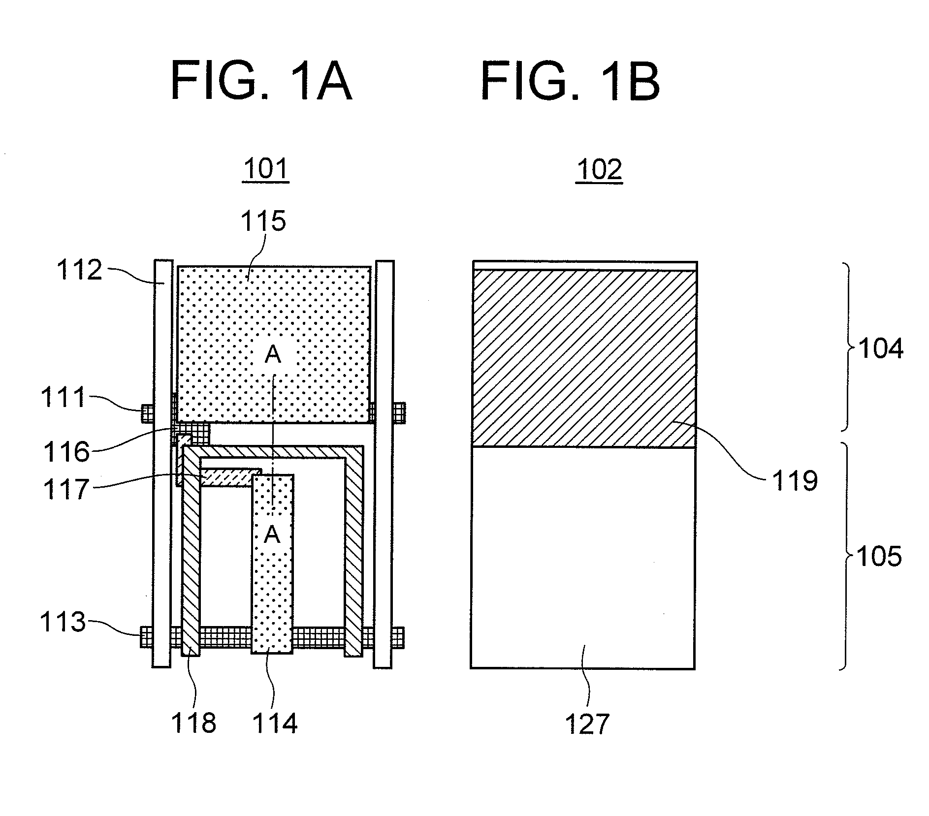
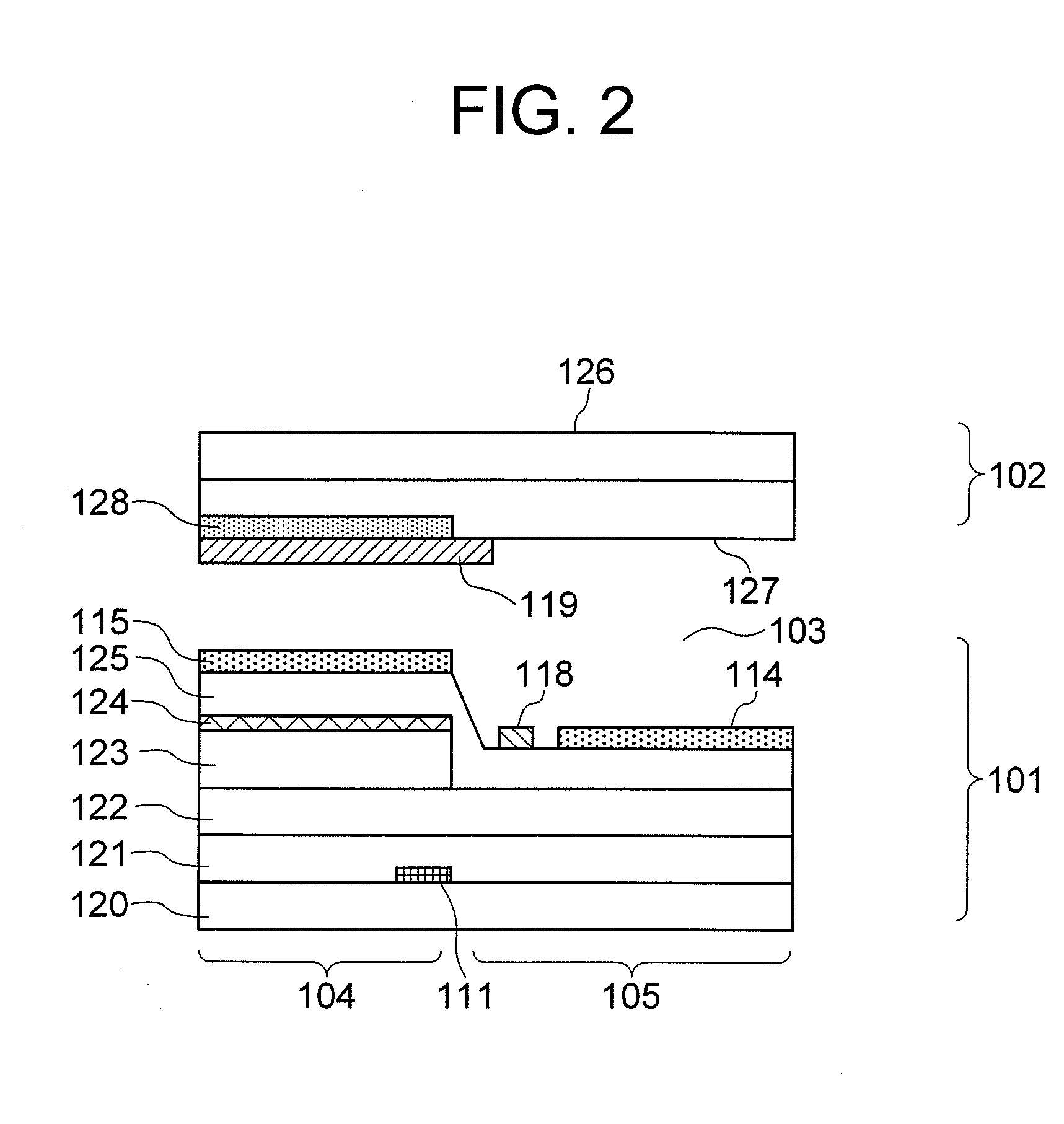
[0033]FIGS. 1A and 1B show, in a top plan view, the TFT substrate and counter substrate, respectively, in a transflective LCD unit according to the present invention. FIG. 2 shows the transflective LCD unit of FIG. 1 in a sectional view. The transflective LCD unit of the present embodiment includes a reflective area 104 and a transmissive area 105 in each unit pixel, wherein the LC layer 103 in the reflective area 104 is driven in a longitudinal-electric-field mode and the LC layer in the transmissive area 105 is driven in a lateral-electric-field mode. An array of unit pixels are arranged in a matrix over the entire screen area of the LCD unit.

[0034]The TFT substrate 101 and the counter substrate 102 oppose each other with an intervention of the LC layer 103. The unit pixel is defined by adjacent two scanning lines 111 extending in the row direction and adjacent two data lines 112 extending in the column direction. The transflective LCD unit of the present embodiment may be used as...

second embodiment

[0065]The present embodiment uses the reflection film 124 as a reverse-tilt control member that controls the reverse tilt area generated in the vicinity of the boundary between the reflective area 104 and the transmissive area 105, and restricts the reverse tilt area to the vicinity of the counter substrate 102. Since the reflection film 124 receives the same signal as that supplied to the reflective-area common electrode 119, there arises a potential difference between the reflection film 124 and the reflective-area pixel electrode 115 upon driving the LC layer 103 by applying a potential difference between the reflective-area pixel electrode 15 and the reflective-area common electrode 119. Since the reflection film 124 overlaps the reflective-area pixel electrode 115 with an intervention of the planarization film 125 therebetween, a longitudinal electric field is generated in the overlapping portion. In addition, in the vicinity of the extension of the reflection film 124 protrudi...


PUM

PropertyMeasurementUnit
voltageaaaaaaaaaa
voltageaaaaaaaaaa
lengthaaaaaaaaaa

Abstract

A transflective LCD unit includes a liquid crystal (LC) layer: first and second substrates sandwiching therebetween the LC layer to define an array of pixels each including a reflective area and a transmissive area; an electrode assembly for driving the LC layer such that the LC layer in the reflective area is driven in a longitudinal-electric-field mode and the LC layer in the transmissive area is driven in a lateral-electric-field mode; and a reverse-tilt control member for controlling a reverse tilt area in which a reverse tilt of LC molecules occurs near the boundary between the reflective area and the transmissive area.

Description

[0001]This application is based upon and claims the benefit of priority from Japanese patent application No. 2007-290978 field on Nov. 8, 2007, the disclosure of which is incorporated herein in its entirety by reference.TECHNICAL FIELD[0002]The present invention relates to a transflective liquid crystal display (LCD) unit and, more particularly, to a transflective LCD unit including a reflective area and a transmissive area 105 in each pixel, wherein the liquid crystal (LC) is driven by a longitudinal electric field in the reflective area, and driven by a lateral electric field in the transmissive area.BACKGROUND ART[0003]A transflective LCD unit which uses a lateral-electric-field mode such as an IPS (in-plane-switching) mode or a FFS (fringe-field-switching) mode is known to have an excellent viewing angle characteristic in the transmissive area. This type of transflective LCD unit is described in Patent Publication-1, for example. The transflective LCD unit described in Patent Pu...

Claims


Application Information

Patent Timeline
Patent Type & Authority Applications(United States)
IPC IPC(8): G02F1/136
CPCG02F1/133555G02F2001/134318G02F1/134363G02F1/133707G02F1/134318
Inventor MORI, KENICHISAKAMOTO, MICHIAKINAGAI, HIROSHI
Owner NEC LCD TECH CORP
Why Eureka
Try Eureka