Multi-layer cascading network bandwidth control

a network bandwidth and cascade technology, applied in the field of computer network control, can solve problems such as the error message generated by the control module, and achieve the effects of improving customer and core network optimization, reducing cost, and improving network throughpu

Inactive Publication Date: 2009-05-14
AT&T SERVICES
View PDF24 Cites 27 Cited by
  • Summary
  • Abstract
  • Description
  • Claims
  • Application Information

AI Technical Summary

Benefits of technology

[0013]Conversely, if bandwidth required at a layer m is reduced, the control module executes the reverse process, where a lower Class of Service can be allocated additional bandwidth in accordance with its requirements. If additional bandwidth is not necessary, the control module can reduce non-preferred route bandwidth, and if this bandwidth drops to zero, free up the route. Accordingly, bandwidth on one or more preferred routes can be reduced.
[0025]Several benefits can be derived from the present invention. For example, intelligent coordination of what have traditionally been multiple uncoordinated, manually provisioned, and / or uncontrollable network layers can be achieved. Furthermore, the present invention can increase customer and core network optimization, as well as improve network throughput and lower cost.

Problems solved by technology

Preferably, if there are no other classes of service available, the control module generates an error message.

Method used


Image

  • Multi-layer cascading network bandwidth control
  • Multi-layer cascading network bandwidth control
  • Multi-layer cascading network bandwidth control

Examples


Embodiment Construction

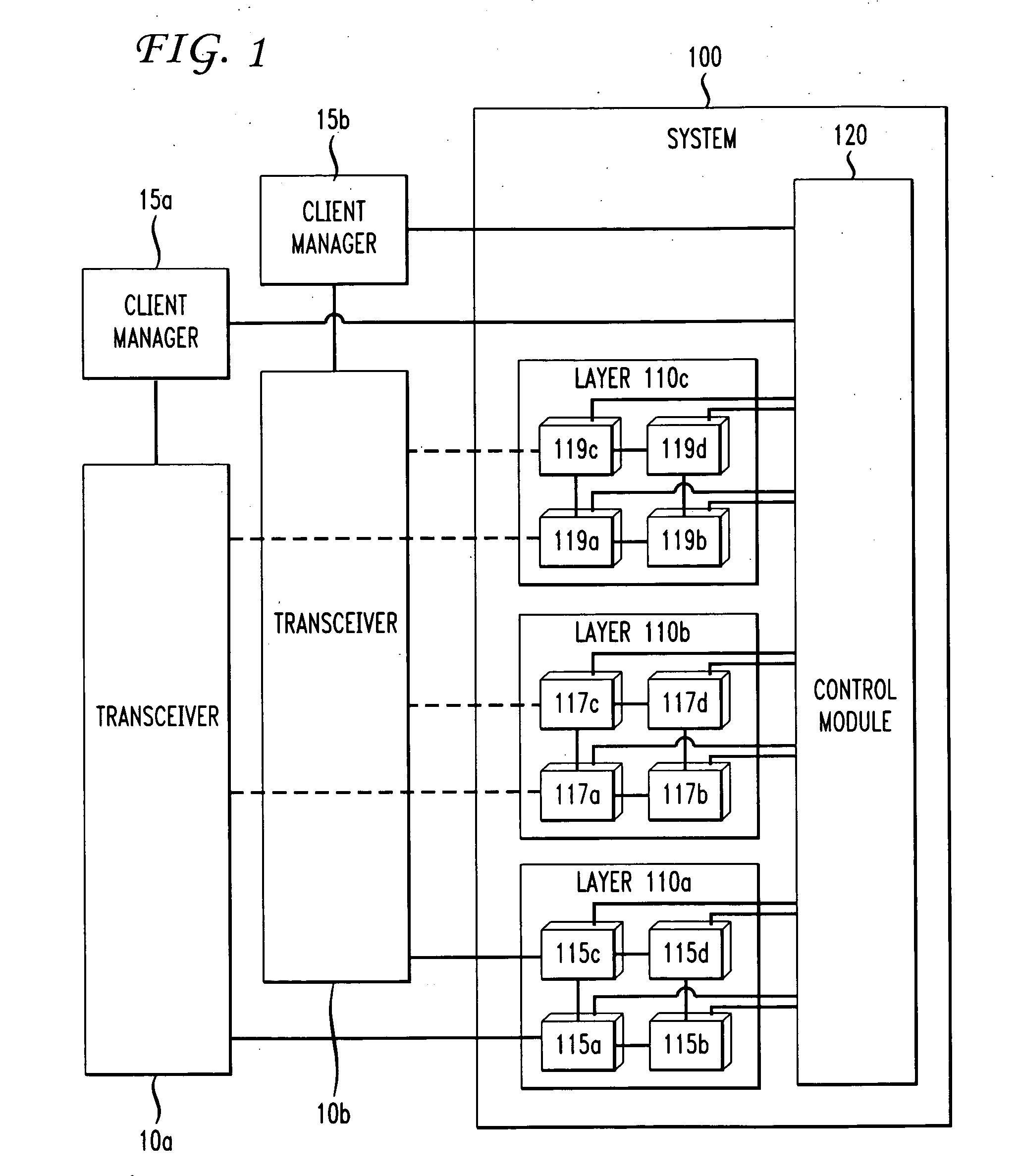
[0031]FIG. 1 illustrates a managed communication system 100 according to the present invention. As shown in FIG. 1, the system 100 can be used in combination with a customer's transmitters, receivers, or both, shown as transceivers 10a and 10b, and client management software 15a and 15b, hereinafter referred to as client managers 15a, 15b, for administration of the network. Although only two transceivers 10a, 10b and client managers 15a, 15b are shown in FIG. 1, the present invention is not limited to two transceivers and two client managers and can include a lesser or greater amount of transceivers and client managers.

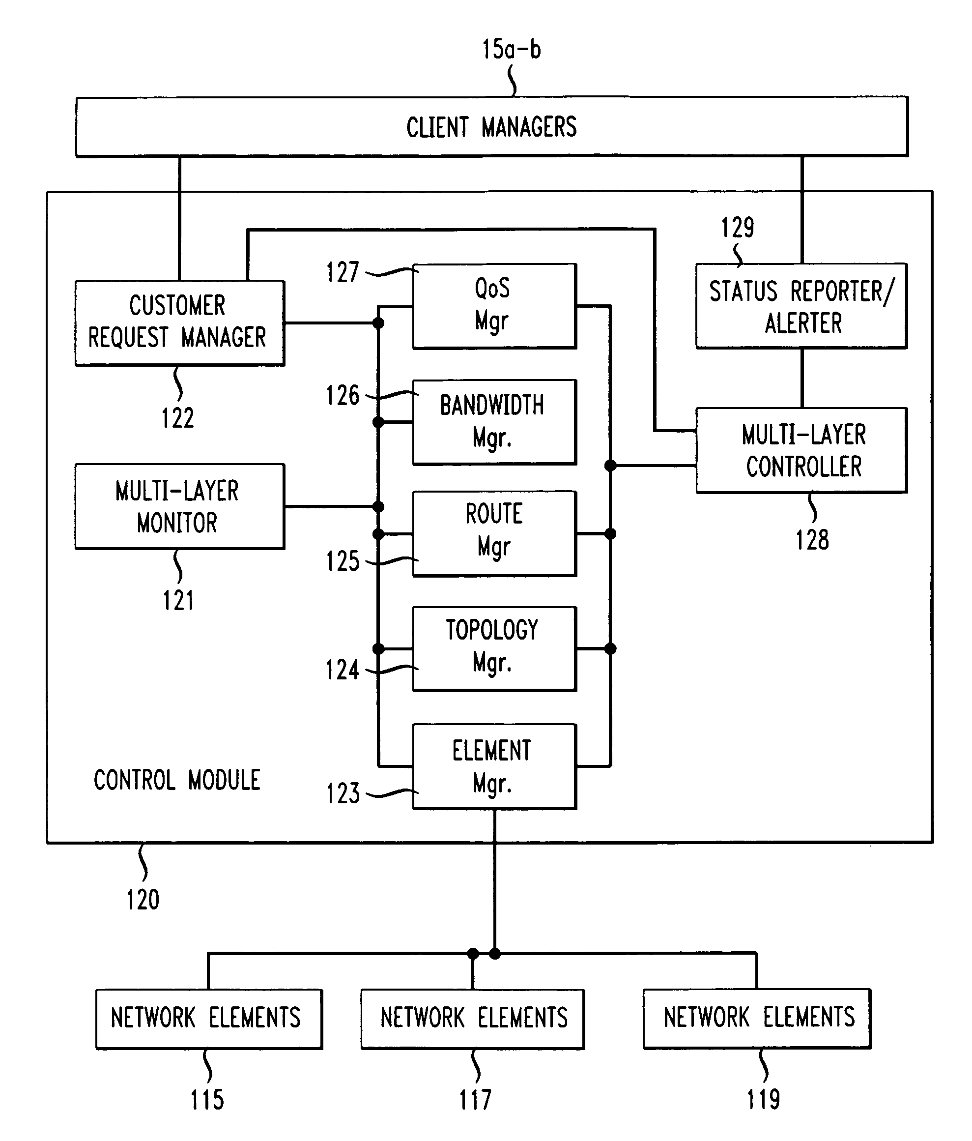
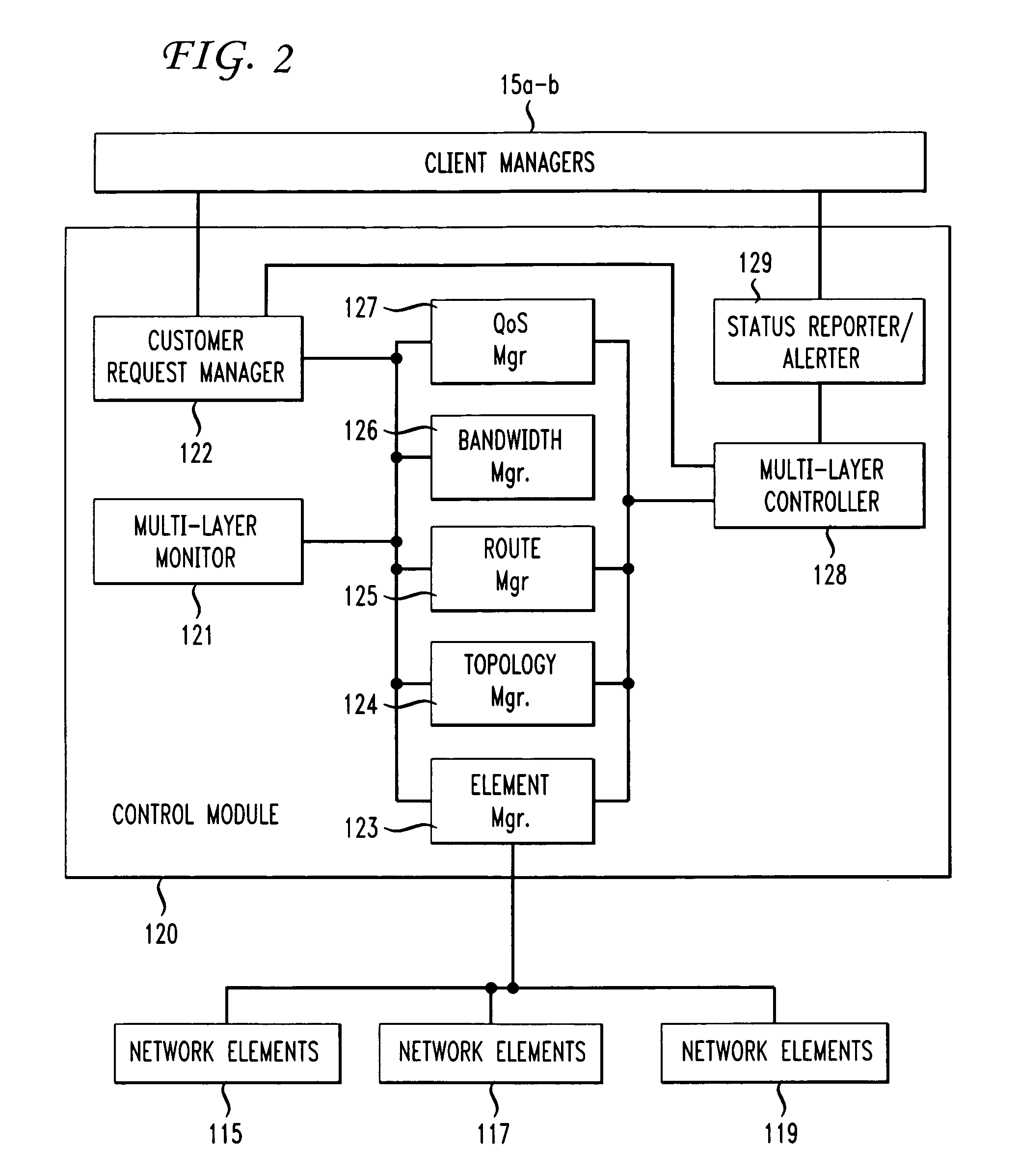
[0032]As shown in FIG. 1, the system 100 includes a set of network layers 110a-c that is operatively coupled to a control module 120. Preferably, the network layers are arranged hierarchically in layers to form a multilayer network. Each network layer 110a-c includes one or more network elements 115a-d, 117a-d, 119a-d. Preferably, network element 119d has greater hier...


PUM


Abstract

A managed communication system is disclosed. The system includes a network having a plurality of layers, such as layers 1, 2, 3, through layer n. Each layer requests and receives services from the layer directly below it. A control module is provided that interacts with the components of each layer. Preferably, each layer exposes one or more flexibility attributes, e.g., route control, bandwidth control, QoS control, or other attributes. A monitoring module is also provided that measures network traffic on ingress to each layer and accepts requirements associated with such traffic

Description

BACKGROUND OF THE INVENTION[0001]1. Field of the Invention[0002]The present invention generally relates to computer network control, and more particularly to coordinated bandwidth control of network layers.[0003]2. Brief Description of the Related Art[0004]Voice, data, and converged voice and data networks are ubiquitous. For example, the Internet permeates virtually everyone's life today. Cellular data services, such as Short Message Service (SMS) and Multimedia Message Service (MMS) are widely used, and private networks, such as Virtual Private Networks (VPNs) are used to connect enterprise data centers, headquarters, branch locations, employees, and partners.[0005]Typically, networks have a layered structure to them. For example, at the lowest layer there may be a photonic mesh where information is transmitted as optical pulses. The information is transmitted with the aid of transport facilities that operate as “pipes” into which a sequence of information is sent. A receiver then...

Claims


Application Information

Patent Timeline
Patent Type & Authority Applications(United States)
IPC IPC(8): G08C15/00
CPCH04L12/5695H04L41/0896H04L41/12H04L47/762H04L41/5087H04L47/10H04L41/5022H04L47/70
Inventor WEINMAN, JOSEPH
Owner AT&T SERVICES
Why Eureka
Try Eureka