Surface acoustic wave transponders

Inactive Publication Date: 2009-05-14
SENSEOR
View PDF11 Cites 13 Cited by
  • Summary
  • Abstract
  • Description
  • Claims
  • Application Information

AI Technical Summary

Problems solved by technology

In a system with narrow band B, the delay τ is, consequently, great and leads to SAW devices that are of large size and therefore costly;the system allows for the simple identification of only one transponder at a time.
To differentiate several transponders, it is necessary:to encode the position of the reflectors so as to obtain delays τ that are variable from one device to another; orto increase the number of reflectors, which leads either to an increase in the length of the transponder or to a greater complexity of the p

Method used


Image

  • Surface acoustic wave transponders
  • Surface acoustic wave transponders
  • Surface acoustic wave transponders

Examples


Embodiment Construction

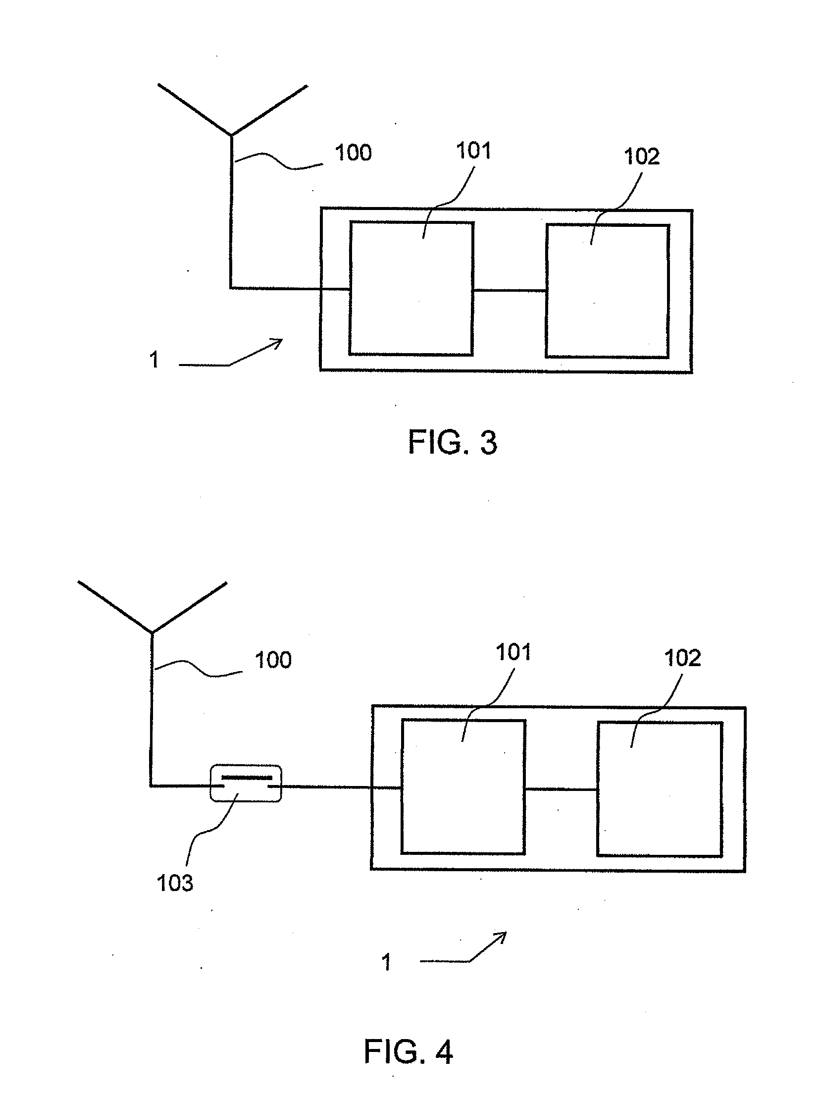
[0062]FIG. 3 represents a transponder 1 according to the invention. It comprises an antenna 100 linked to a dipole-type SAW device, itself comprising a cascaded narrow-band filter 101 and delay line 102 with total reflection.

[0063]In the case where the transponders 1 have only one single narrow-band filter, it is entirely defined by its reflection-mode transfer function. Its main characteristics are:[0064]the central frequency F which is the parameter identifying the transponder;[0065]the bandwidth B which is F / Q, Q being the quality factor of the resonator;[0066]the attenuated band of width 2Δf, Δf being the minimum difference making it possible to unambiguously differentiate two frequencies F1 and F2 corresponding to two different transponders;[0067]the transit time τ of the reflection-mode delay line.

[0068]Advantageously, the transponder can comprise a number of electronic filters with narrow spectral band, each spectral band of each filter being centered on a different central f...


PUM


Abstract

The field of the invention is that of surface acoustic wave transponders and associated devices. This invention applies more particularly to the techniques for identifying and locating transponders. It also applies to the transmission of information or measurements, the transponder then being used as a transducer. This type of transponder can, in particular, be used on vehicles, and in particular on road vehicles. The inventive transponder (1) comprises a surface acoustic wave device, comprising one or more electronic filters (101) with narrow spectral band centered on one or more central frequencies and a delay line (102) operating in reflection mode. By having narrowband filters centered on different frequencies, it is thus possible to easily discriminate between different transponders. The delay lines make it possible to simply separate the transmitted signal and the received signal. The inventive transponder can also be used as a transducer. Also, by using an interrogation device that uses two receive antennas, it is possible to locate the position of several transducers with a single interrogation device.

Description

CROSS-REFERENCE TO RELATED APPLICATIONS[0001]The present application is based on International Application No. PCT / EP2005 / 056779, filed on Dec. 14, 2005, which in turn corresponds to French Application No. 04 13336 filed on Dec. 15, 2004 and priority is hereby claimed under 35 USC § 119 based on these applications. Each of these applications are hereby incorporated by reference in their entirety into the present application.FIELD OF THE INVENTION[0002]The field of the invention is that of surface acoustic wave transponders and associated devices. This invention applies more particularly to the techniques of identifying and locating transponders. It also applies to the transmission of information or measurements, the transponder then being used as a transducer.[0003]This type of transponder can, in particular, be used on vehicles, and in particular on road vehicles.BACKGROUND OF THE INVENTION[0004]The surface acoustic wave (SAW) devices are used to produce remote interrogation system...

Claims


Application Information

Patent Timeline
IPC IPC(8): G01K7/32H01L41/107
CPCG06K19/0672
Inventor CHOMIKI, MICHEL
Owner SENSEOR
Why Eureka
Try Eureka