Turbine or compressor stage for a turbojet

a compressor stage and turbojet technology, applied in the direction of machines/engines, snap fasteners, liquid fuel engines, etc., can solve the problems of increasing the strain on the median portion of the lock, not being radially immobilized correctly, and vibrating in the operating state, so as to achieve simple, efficient and cost-effective

Active Publication Date: 2009-05-14
SN DETUDE & DE CONSTR DE MOTEURS DAVIATION S N E C M A
View PDF6 Cites 7 Cited by
  • Summary
  • Abstract
  • Description
  • Claims
  • Application Information

AI Technical Summary

Benefits of technology

[0010]According to the invention, the heat shielding foil comprises a portion of greater thickness, or radial dimension, which extends toward the device and is adapted to radially bear against this device to radially immobilize the foil, or the inner wall of the device comprises a portion of greater thickness, or radial dimension, which extends toward the foil and is adapted to radially bear against this foil to immobilize it in a radial direction. This radial bearing provides a small radial preload for the foil which is then radially immobilized and prevented from vibrate in the operating state of the turbojet.
[0013]The locking device can comprise only one annular protuberance which extends on 360°, or circumferential protuberances which are spaced one from the others by a distance. The, or each, protuberance allows for the device to be rigidified in order to further withstand the strains communicated by the ring sector in the operating state. The circumferential protuberances allow for the amount of material needed to provide the radial extra thickness of the device to be limited. They can be provided by machining, e.g. by milling, the inner wall of the device.
[0016]The protuberance of each lock extends for example in a circumferential direction on at least a part of the width, or angular extent, of the lock in order to cause a small weight variation for this lock.
[0017]This protuberance is preferably formed on a median portion of the inner wall of the lock. In that last instance, the protuberance reinforces the median portion of the lock which can then withstand the stresses communicated by the median portion of the ring sector and counter the discambering of this ring sector. One can then notice small variations of the radial backlash between the crests of the vanes of the rotor disk and the ring sectors, which improves the performances of the turbojet.

Problems solved by technology

However, it is not correctly radially immobilized and can then vibrate in the operating state, and be damaged.
This phenomenon essentially produces into an increase of the curvature radius of the ring sector, which increases the strains in the median portion of the lock and can reduce its lifetime.

Method used


Image

  • Turbine or compressor stage for a turbojet
  • Turbine or compressor stage for a turbojet
  • Turbine or compressor stage for a turbojet

Examples


Embodiment Construction

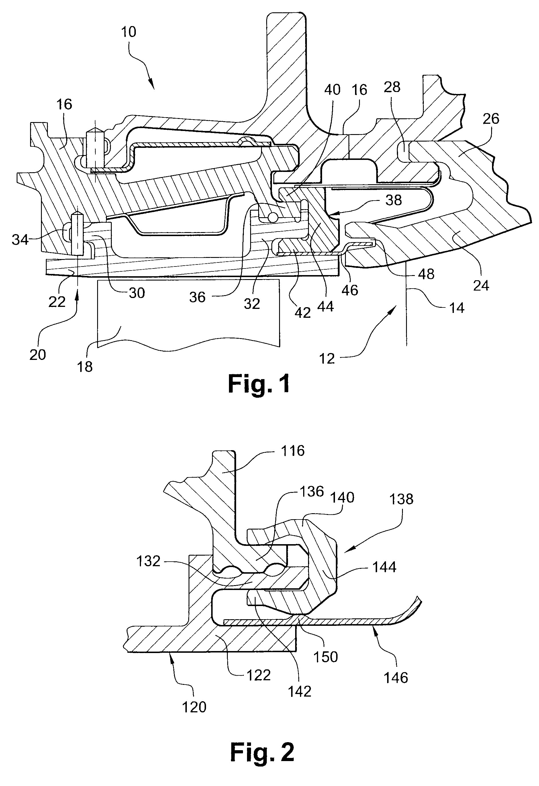
[0026]Referring first to FIG. 1, it shows a turbine stage 10 for a turbojet, comprising a distributor 12 made up of an annular row of fixed vanes 14 supported by a casing 16 of the turbine, and a rotor disk 18 mounted upstream from the distributor 12 and rotating in a sectorized ring 20 made up of a plurality of sectors 22 which are circumferentially supported, in an abutting manner, on the casing 16 of the turbine.

[0027]The distributor 12 comprises two respectively outer 24 and inner (not shown) annular walls, which delimit therebetween the annular stream of gases in the turbine and between which the vanes 14 radially extend. The outer wall 24 of the distributor comprises a cylindrical flange 26 directed upstream and adapted to be engaged in an annular groove 28 directed downstream from the casing 16.

[0028]Each ring sector 22 comprises a circumferentially directed wall which comprises, at its upstream and downstream ends, circumferential flanges 30, 32 hooking on the casing 16 of t...


PUM


Abstract

A turbojet turbine or compressor stage, comprising at least one rotor disk mounted inside a sectorized ring (120) supported by a casing (116) and comprising a circumferential flange (132) radially clamped on an annular rail (136) of the casing by a substantially C-shaped cross-section annular locking device (138) which is axially engaged on the casing rail and on the flange of the ring, a substantially cylindrical heat shielding foil (146) being interposed between the ring and the device, the foil, or the device, comprising at least one extra thickness (150) which respectively bears on the device, or the foil, to radially immobilize this foil.

Description

[0001]The present invention relates to a turbine or compressor stage, particularly for a plane turbojet.TECHNOLOGICAL BACKGROUND OF THE INVENTION[0002]A stage of this type comprises a distributor formed by a row of annular fixed guide vanes supported by a casing of the compressor or the turbine, and a rotor disk mounted upstream from the distributor inside a sectorized ring hooked on the casing.[0003]The distributor comprises two respectively inner and outer annular walls, the fixed guide vanes extending therebetween.[0004]The ring comprises, at one end thereof, a circumferential flange which is radially clamped on an annular rail of the casing through a substantially C-shaped cross-section annular locking device, which is axially engaged on the casing rail and on the circumferential flange of the ring. The locking device comprises two annular walls, respectively inner and outer, which are connected together through a substantially radial wall. This device is sectorized and made up ...

Claims


Application Information

Patent Timeline
Patent Type & Authority Applications(United States)
IPC IPC(8): F04D29/58
CPCF01D11/08Y10T24/44744F05D2240/11Y02T50/671Y02T50/60
Inventor AUDEON, DAVIDDA SILVA, DAVID
Owner SN DETUDE & DE CONSTR DE MOTEURS DAVIATION S N E C M A
Why Eureka
Try Eureka