
Mobile communication system and base station
- Summary
- Abstract
- Description
- Claims
- Application Information
AI Technical Summary
Benefits of technology
Problems solved by technology
Method used
Image

Examples
first embodiment
(B) First Embodiment
(a) Configuration of Base Station
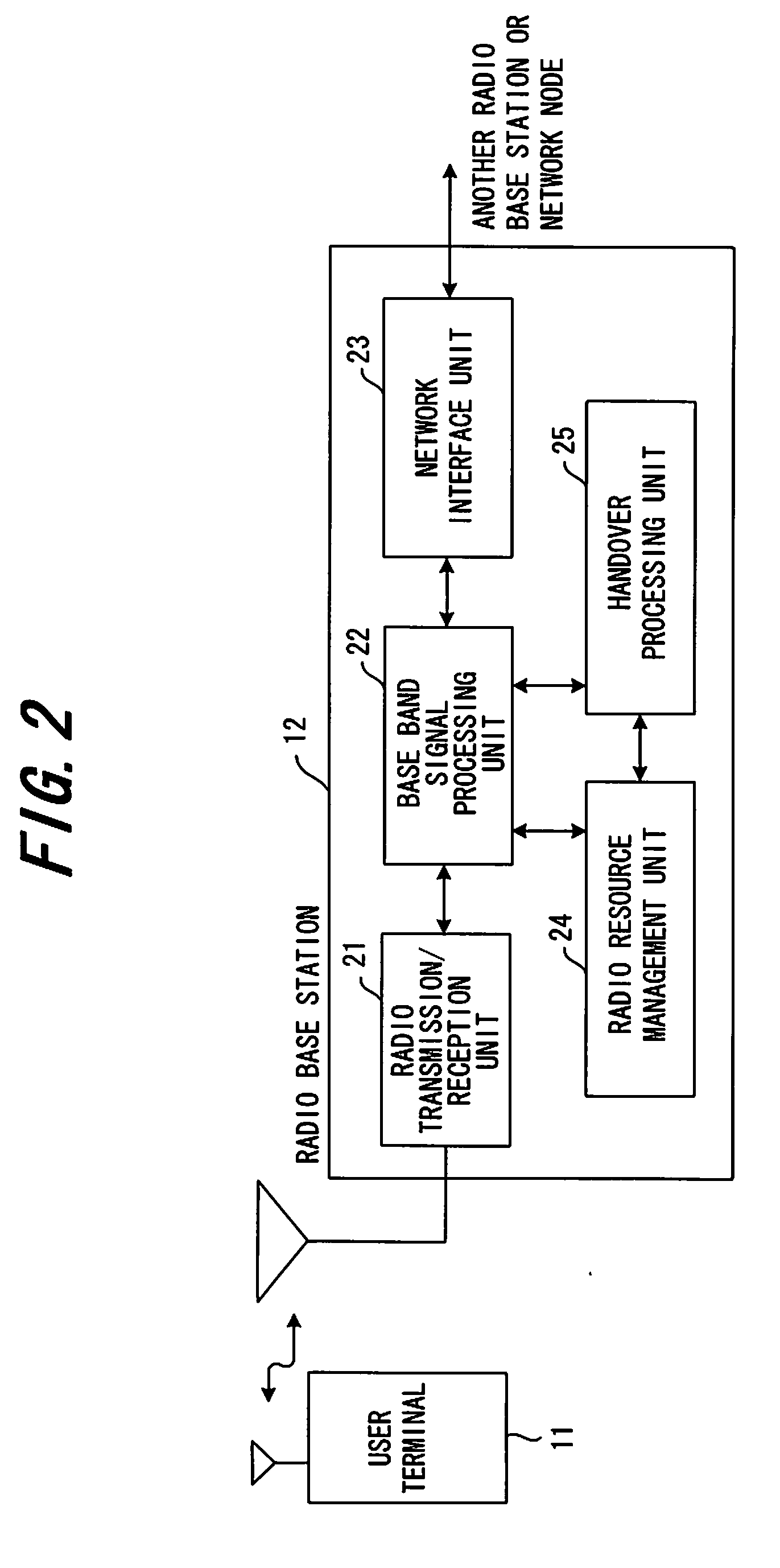
[0055]FIG. 2 is a block diagram showing a radio base station 12 of a first embodiment, which has a radio transmission / reception unit 21, a base band signal processing unit 22, a network interface unit (network IF unit) 23, a radio resource management unit 24 and a handover processing unit 25.
[0056]The radio transmission / reception unit 21 converts the frequency of a signal, generated by the base band signal Processing unit 22 which performs base band signal processing, into a radio frequency, and transmits it via an antenna. The radio transmission / reception unit 21 also detects the receive signal, converts it into a base band signal, and inputs it to the base band signal processing unit 22. The network IF unit 23 controls the transmission / reception of control data and user data between the radio base station 12 and a base station control device (network node) or another radio base station, and transmits / receives user data and contr...
second embodiment
(C) Second Embodiment
[0100]A second embodiment controls the transmission power of a radio resource in parallel with the control of the first embodiment or each variant form thereof.
[0101]FIG. 13 is a block diagram showing a radio resource management unit of the second embodiment, where the same composing elements as the radio resource management unit 24 (FIG. 5) of the first embodiment are denoted with the same symbols. The difference is that the second embodiment has an RB number / transmission power correspondence table creation unit 24f and a transmission power control unit 27. The RB number / transmission power correspondence table PWTB is for specifying a transmission power upper limit value according to the cumulative count of the RB number determined by the RB number / cumulative count correspondence table TB, and as the cumulative count is lower, the transmission power upper limit value of the resource block increases.
[0102](A) and (B) of FIG. 14 show the correspondence of the RB ...
third embodiment
(D) Third Embodiment
[0111]As FIG. 19 shows, the shape of a cell is not always regular form (e.g. circle, hexagon) in an actual geometric environment. In the third embodiment, each base station knows the shape of its own cell by collecting position information from the handover user. And, based on the shape of its own cell, the base station identifies in which of the cell center area ranges A1 to An the mobile terminal exists, and performs resource assignment control and transmission power control of the first embodiment and second embodiment.
[0112]FIG. 20 is a block diagram showing a base station of the third embodiment, where the same composing elements as the base station of the first embodiment in FIG. 2 are denoted with the same symbols. The difference from FIG. 2 is that the position information management unit 31 is disposed so as to collect position information from the mobile terminal during handover, and to specify the cell shape of the base station based on the collected p...
PUM
 Abstract
Description
Claims
Application Information