Hybrid vehicle with internal combustion engine and electric motor installed

a hybrid vehicle and electric motor technology, applied in the direction of engine-driven generators, propulsion parts, process and machine control, etc., can solve the problem that the operation/stop of the engine is not always suitable for the driver's sense of direction

Inactive Publication Date: 2009-05-14
TOYOTA JIDOSHA KK
View PDF0 Cites 91 Cited by
  • Summary
  • Abstract
  • Description
  • Claims
  • Application Information

AI Technical Summary

Benefits of technology

[0009]Therefore, an object of this invention is to provide a hybrid vehicle capable of more properly notifying a driver of timing at which an internal combustion engine is operated / stopped.

Problems solved by technology

Therefore, using the accelerator pedal position as a parameter for notifying the driver of timing at which the engine is operated / stopped is not always fit for a sense of the driver.

Method used


Image

  • Hybrid vehicle with internal combustion engine and electric motor installed
  • Hybrid vehicle with internal combustion engine and electric motor installed
  • Hybrid vehicle with internal combustion engine and electric motor installed

Examples


first embodiment

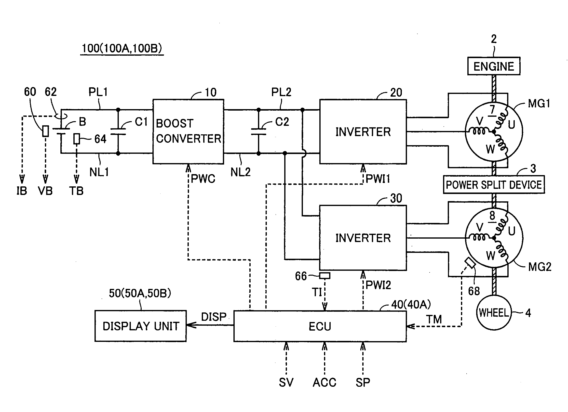
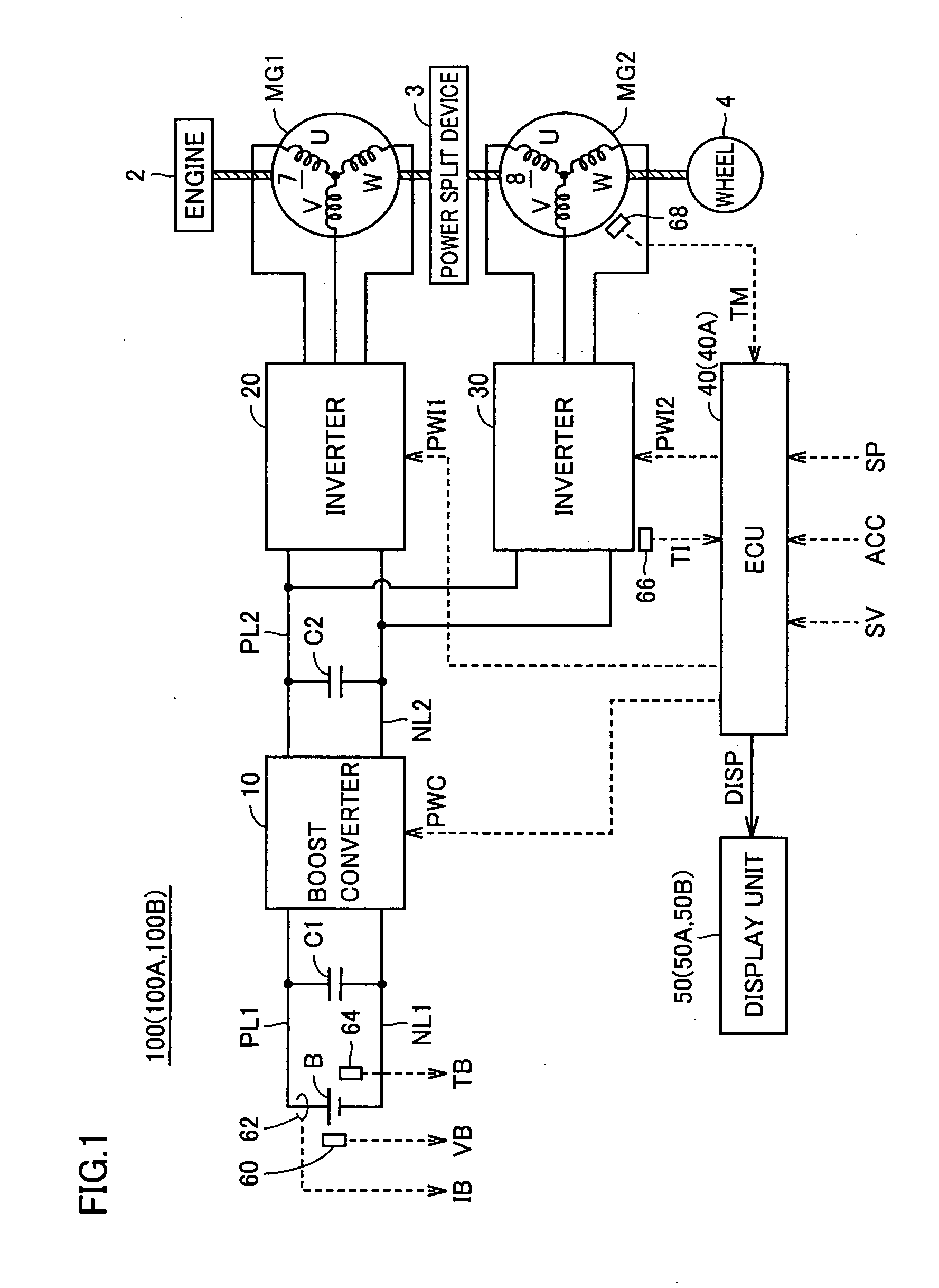
[0037]FIG. 1 is a function block diagram showing the entire configuration of a hybrid vehicle according to a first embodiment of this invention. With reference to FIG. 1, this hybrid vehicle 100 is provided with an engine 2, motor generators MG1 and MG2, a power split device 3, and a wheel 4. Hybrid vehicle 100 is further provided with a power storage device B, a boost converter 10, inverters 20 and 30, capacitors C1 and C2, an ECU (Electronic Control Unit) 40, and a display unit 50. Moreover, hybrid vehicle 100 is further provided with a voltage sensor 60, a current sensor 62, and temperature sensors 64, 66 and 68.

[0038]Engine 2 and motor generators MG1 and MG2 are linked to power split device 3. Then, hybrid vehicle 100 travels by drive force from motor generator MG2 and / or engine 2. Motive power generated by engine 2 is split into two routes by power split device 3. That is, one is the route to be transmitted to wheel 4, and the other is the route to be transmitted to motor gener...

second embodiment

[0069]In this second embodiment, the switching between traveling only with motor generator MG2 while stopping engine 2 (EV traveling) and traveling with operating engine 2 (HV traveling) is controlled based on the vehicle speed and vehicle power. Then, a display unit displays the vehicle speed and the engine non-operation vehicle speed threshold value and further displays the vehicle power and an engine non-operation power threshold value corresponding to the vehicle power.

[0070]With reference to FIG. 1 again, a hybrid vehicle 100A according to this second embodiment is provided with an ECU 40A and a display unit 50A instead of ECU 40 and display unit 50 respectively in the configuration of hybrid vehicle 100 according to the first embodiment shown in FIG. 1.

[0071]ECU 40A calculates vehicle demand power, and controls the switching between traveling only with motor generator MG2 while stopping engine 2 (EV traveling) and traveling with operating engine 2 (HV traveling) based on the c...

third embodiment

[0091]In the second embodiment, the vehicle speed and the vehicle power are displayed on separate meters. However, in this third embodiment, the vehicle speed and the vehicle power are two-dimensionally displayed on one meter.

[0092]A hybrid vehicle 100B according to this third embodiment is provided with a display unit 50B instead of display unit 50A in the configuration of hybrid vehicle 100A according to the second embodiment. Display unit 50B two-dimensionally displays the vehicle speed and the vehicle power and displays the engine non-operation threshold values while indicating the movement direction thereof based on the engine non-operation vehicle speed threshold value, the engine non-operation power threshold value and the change amounts of the threshold values received from ECU 40A.

[0093]FIG. 7 is a view showing a display state of display unit 50B in the third embodiment. With reference to FIG. 7, display unit 50B includes a speed / power display unit 130. Speed / power display ...


PUM


Abstract

A display unit includes a speed display unit. The speed display unit includes an area, a threshold line and a pointer. The area indicates a vehicle speed (km/h). The threshold line indicates a threshold value at which operation and stop of an engine is switched. The threshold line is variably set by SOC and a temperature of a power storage device, a temperature of an inverter, a temperature of a motor generator and the like. The pointer indicates the movement direction of the threshold line.

Description

[0001]This nonprovisional application is based on Japanese Patent Application No. 2007-290799 filed on Nov. 8, 2007 with the Japan Patent Office, the entire contents of which are hereby incorporated by reference.BACKGROUND OF THE INVENTION[0002]1. Field of the Invention[0003]This invention relates to a hybrid vehicle, particularly to a hybrid vehicle with an internal combustion engine and an electric motor installed as a power source for traveling.[0004]2. Description of the Background Art[0005]A hybrid vehicle draws attention as an eco-friendly automobile. In the hybrid vehicle, an electric motor driven by an inverter with using electric power stored in a power storage device is further installed as a power source in addition to a conventional engine.[0006]When vehicle demand power is small, the engine is stopped and this hybrid vehicle travels only by the electric motor (electric motor traveling). When the vehicle demand power is increased, the engine is operated and the hybrid ve...

Claims


Application Information

Patent Timeline
Patent Type & Authority Applications(United States)
IPC IPC(8): B60W20/00G07C5/00B60L50/16
CPCB60K6/445B60W2050/146B60L2240/425B60W10/06B60W10/08B60W10/26B60W20/00B60W2510/087B60W2510/244B60W2510/246B60W2520/10B60Y2200/90Y02T10/6286Y02T10/642Y02T10/48Y02T10/6239B60K35/00B60L7/10B60L15/20B60L2240/12B60L2240/14B60L2240/421B60L2240/423B60L2240/441B60L2240/443B60L2240/545B60L2240/547B60L2240/549B60L2250/16B60L2250/26B60L50/16B60L50/61B60L58/12B60L58/25Y02T10/40Y02T10/62Y02T10/64Y02T10/70Y02T10/7072Y02T10/72B60W20/13
Inventor KOMATSU, MASAYUKIKUBO, KAORU
Owner TOYOTA JIDOSHA KK
Why Eureka
Try Eureka