Storage control apparatus, storage system, and virtual volume control method

a storage system and control apparatus technology, applied in the direction of memory address/allocation/relocation, instruments, computing, etc., can solve the problems of insufficient protection, failure of redundancy protection of storage area management table, and no longer possible to input and output data to and from the virtual volume, so as to improve reliability and efficiently use the storage area

Active Publication Date: 2009-05-14
HITACHI LTD
View PDF4 Cites 38 Cited by
  • Summary
  • Abstract
  • Description
  • Claims
  • Application Information

AI Technical Summary

Benefits of technology

[0019]The present invention was conceived in view of the above problem and an object thereof is to provide a storage control apparatus, storage system, and virtual volume control method which make it possible to maintain conformity between the storage area management table and the write data stored in the real storage area and to improve reliability. A further object of the present invention is to provide a storage control apparatus, storage system, and virtual volume control method that make it possible to maintain the conformity between the storage area management table and the write data stored in the real storage area and to use the storage area efficiently. Further objects of the present invention will become evident from the embodiments described hereinbelow.

Problems solved by technology

However, the specification of Patent Application No. 2007-013384 has not yet been published and does not apply to conventional technology.
The real storage area assigned to the virtual volume is managed by the storage area management table and, therefore, in cases where the storage area management table fails, it is no longer possible to input and output data to and from the virtual volume.
However, with respect to the method of saving the storage area management table only in the memory in the controller, it cannot be said that the protection is adequate.
In cases where a fault is generated in one of the duplicate memories or where an anomaly is produced in the battery, the redundancy of the protection of the storage area management table has failed.
However, the timing of writing and saving the storage area management table in the storage device and the timing of writing the user data (write data) written to the virtual volume to the storage device do not necessarily match one another.
Although the de-staging processing for the write data ends normally, in cases where the de-staging processing for the storage area management table has not ended normally for whatever reason, the content of the storage area management table and the storage state of the write data no longer conform.
When a real storage area that has already been used is used to process another write command, the write data stored in the real storage area are lost.
Thus, maintaining a more sufficient degree of protection for the storage area management table and maintaining conformity between the storage area management table and the data stored in the real storage area are an important problem for the storage control apparatus which provides the virtual volume.
Therefore, the advantage of a virtual volume that allows only the required real storage area to be used as required by the backup destination storage control apparatus is lost and the storage area cannot be used efficiently.

Method used


Image

  • Storage control apparatus, storage system, and virtual volume control method
  • Storage control apparatus, storage system, and virtual volume control method
  • Storage control apparatus, storage system, and virtual volume control method

Examples


first embodiment

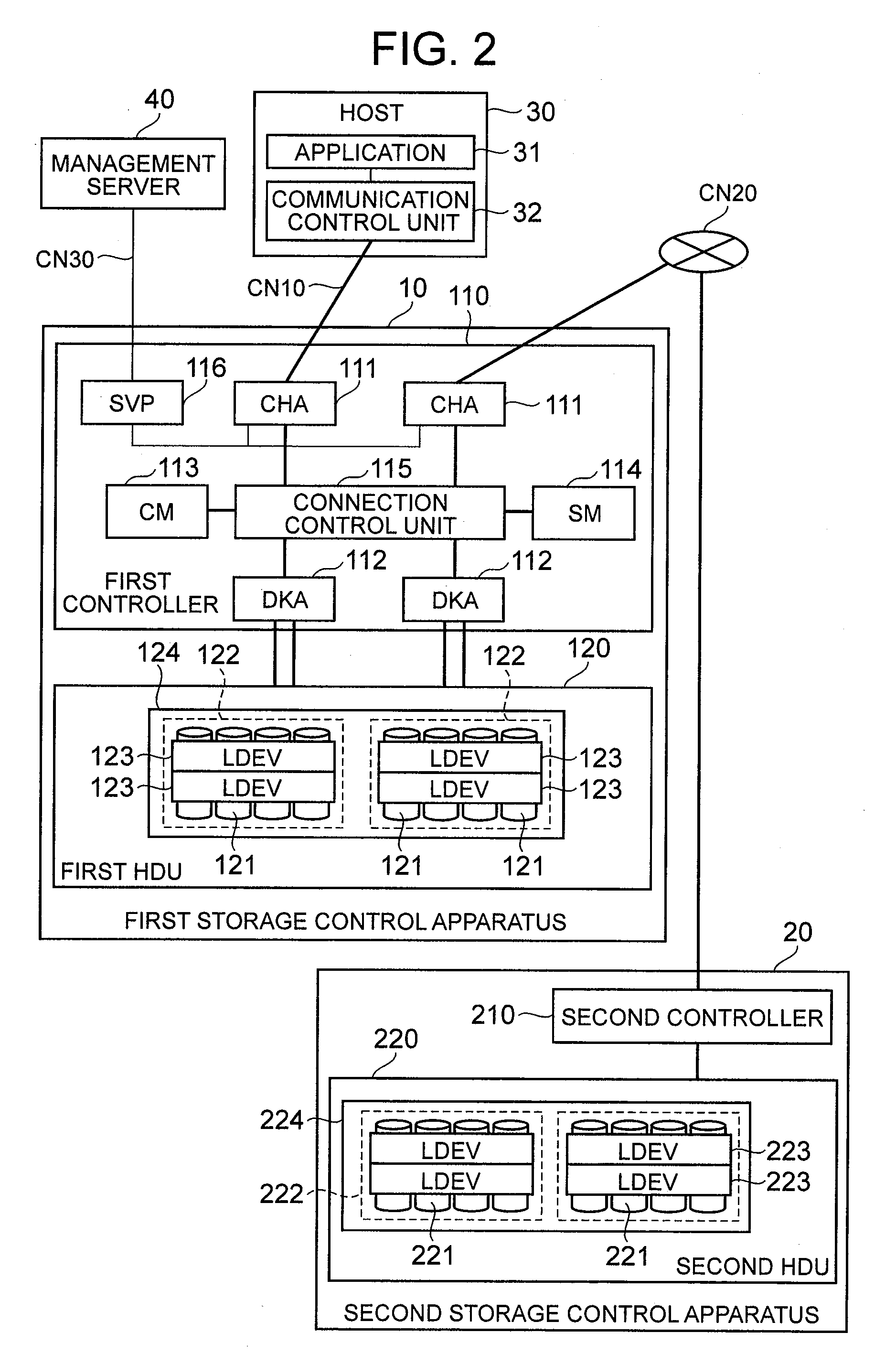
[0092]FIG. 2 is an explanatory diagram that provides an overview of the storage system according to this embodiment. This embodiment describes a case where a first storage control apparatus 10 incorporates and uses the real storage area of a second storage control apparatus 20.

[0093]From the perspective of the first storage control apparatus 10, the second storage control apparatus 20 is a storage control apparatus that exists outside the first storage control apparatus 10. Hence, the second storage control apparatus 20 can also be called an external storage control apparatus. In this embodiment, the first storage control apparatus 10 generates a virtual volume by using a real storage area of the second storage control apparatus 20. Host 30 is able to see data being read from and written to the virtual volume in the first storage control apparatus 10 but the actual storage destination of the data is the real storage area in the second storage control apparatus 20. Thus, a constituti...

second embodiment

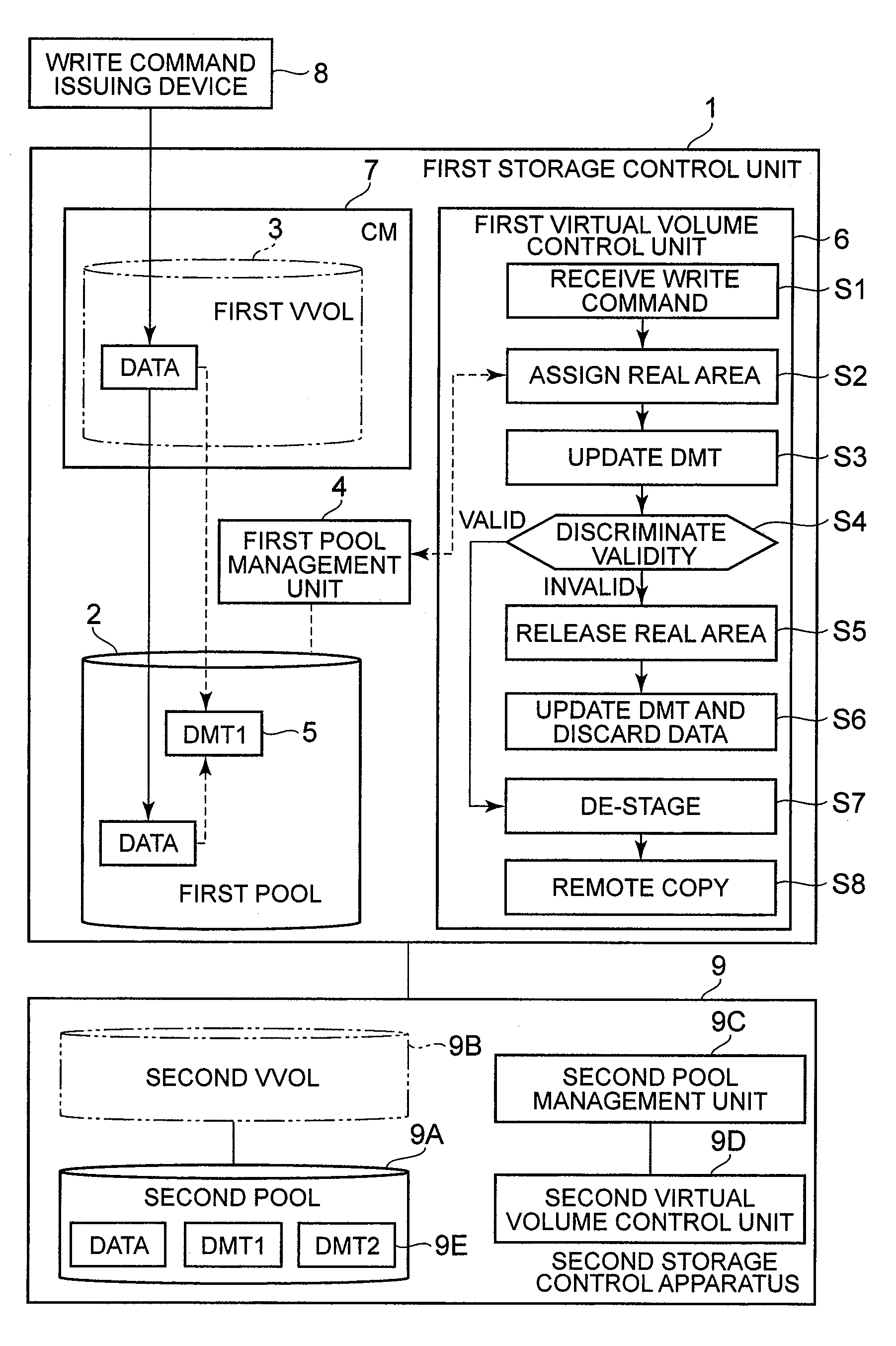
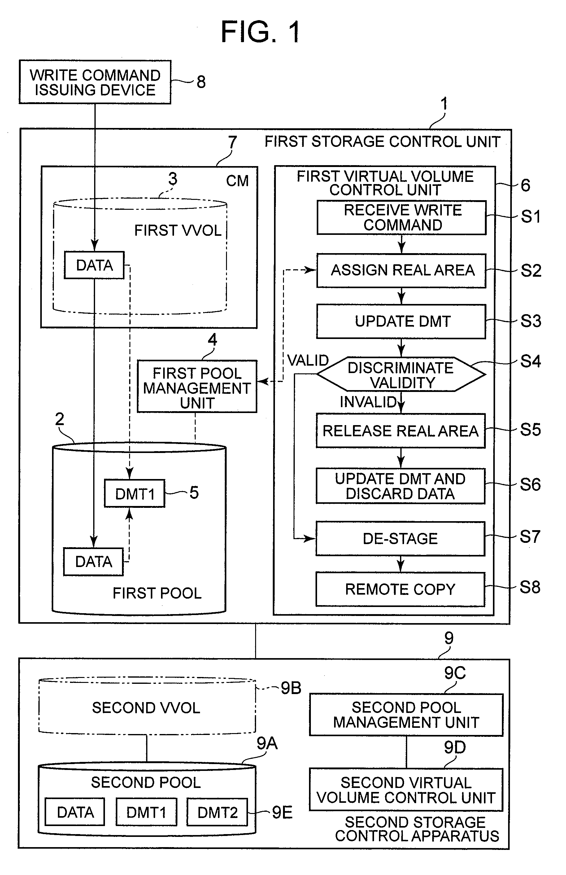
[0169]The second embodiment will now be described on the basis of FIGS. 10 to 18. Each of the following embodiments including this embodiment corresponds to a modified example of the first embodiment. Descriptions which overlap with the first embodiment will be omitted hereinbelow. In this embodiment, a copy pair is formed by the first virtual volume 140 in the first storage control apparatus 10 and the second virtual volume 240 in the second storage control apparatus 20. Data are copied between the virtual volumes.

[0170]FIG. 10 is an overall constitutional view of the storage system according to this embodiment. The second storage control apparatus 20 of this embodiment comprises a second virtual volume 240. A real slot in the second pool 224 is assigned to the second virtual volume 240. The real slot in the first pool 124 is assigned to the first virtual volume 140 of the first storage control apparatus 10. The first virtual volume 140 and second virtual volume 240 form a copy pai...

third embodiment

[0215]The third embodiment will now be described on the basis of FIG. 19. In this embodiment, a backup device 50 is used in place of the second storage control apparatus 20. The backup device 50 comprises a controller 51 and a backup storage device 52, for example. The backup storage device 52 is constituted as a magnetic tape device and a hard disk device, for example. The controller 51 controls the operation of the backup storage device 52.

[0216]The data which are stored in the first virtual volume 140 are copied to the backup device 50 at the designated backup time (S110). During the restore, the data stored in the backup device 50 are written to the first virtual volume 140 (S111).

[0217]A copy from the first storage control apparatus 10 to the backup device 50 (S110) can be performed in the same manner as the processing shown in FIG. 15. A copy from the backup device 50 to the first storage control apparatus 10 can be executed in the same way as the processing shown in FIG. 17. ...


PUM


Abstract

The storage control apparatus of the present invention saves a table for managing a virtual volume in a pool and keeps the state of the table in the latest state. A first dynamic mapping table (DMT) that manages a first virtual volume is saved in a first pool. Upon receipt of a write command relating to an unused virtual slot from a write command issuing device, a first virtual volume control unit assigns an unused real slot in the first pool to the virtual slot and updates the first DMT. The first virtual volume control unit discriminates the validity of the received data and, in cases where “0” data are received, releases the assigned real slot, updates the first DMT once again, and discards the received data. In cases where the received data are valid data, de-staging is performed following a DMT update.

Description

CROSS-REFERENCE TO RELATED APPLICATIONS[0001]This application relates to and claims priority from Japanese Patent Application No. 2007-292090 filed on Nov. 9, 2007, the entire disclosure of which is incorporated herein by reference.BACKGROUND OF THE INVENTION[0002]1. Field of the Invention[0003]The present invention relates to a storage control apparatus, a storage system, and a virtual volume control method.[0004]2. Description of the Related Art[0005]In order to handle large quantities of data of multiple types at government agencies, enterprises, and educational establishments, for example, data are managed using a relatively large-scale storage system. This storage system comprises at least one storage control apparatus. The storage control apparatus comprises a multiplicity of storage devices, for example, and is able to provide a RAID (Redundant Array of Inexpensive Disks)-based storage area. At least one or more logical devices (also known as logical volumes) are formed in a ...

Claims


Application Information

Patent Timeline
Patent Type & Authority Applications(United States)
IPC IPC(8): G06F12/02G06F12/06
CPCG06F12/023
Inventor INNAN, MASATAKATABUCHI, HIDEO
Owner HITACHI LTD
Why Eureka
Try Eureka