Air Flow Measuring Instrument

a technology of air flow and measuring instruments, which is applied in the direction of instruments, volume/mass flow measurement, measurement devices, etc., can solve the problems of difficult to perform stable measurement using fluid exfoliation turbulence, and achieve the effect of preventing damage or contamination of fluid measuring elements comprised by heating resistor patterns or the lik

Inactive Publication Date: 2009-05-21
HITACHI LTD
View PDF18 Cites 25 Cited by
  • Summary
  • Abstract
  • Description
  • Claims
  • Application Information

AI Technical Summary

Benefits of technology

[0012]According to the present invention, after dust bounces off an upstream-side end of a tabular member, the dust can be inhibited from travelling in the flow of a fluid to flow to a surface side on which a heating resistor pattern of a tabular member is provided, and thus damage or contamination of a fluid measuring element comprised by a heating resistor pattern or the like can be prevented.

Problems solved by technology

According to the conventional technology, although there is an effect to protect the air flow measuring element from dust and the like, because the adopted configurations are those in which the surface on which the air flow measuring element is disposed is hidden with respect to the flow, there is the problem that, with regard to the flow rate that should primarily be measured, it is difficult to perform stable measurement using turbulence by exfoliation flow of fluid or the like.

Method used


Image

  • Air Flow Measuring Instrument
  • Air Flow Measuring Instrument
  • Air Flow Measuring Instrument

Examples


examples

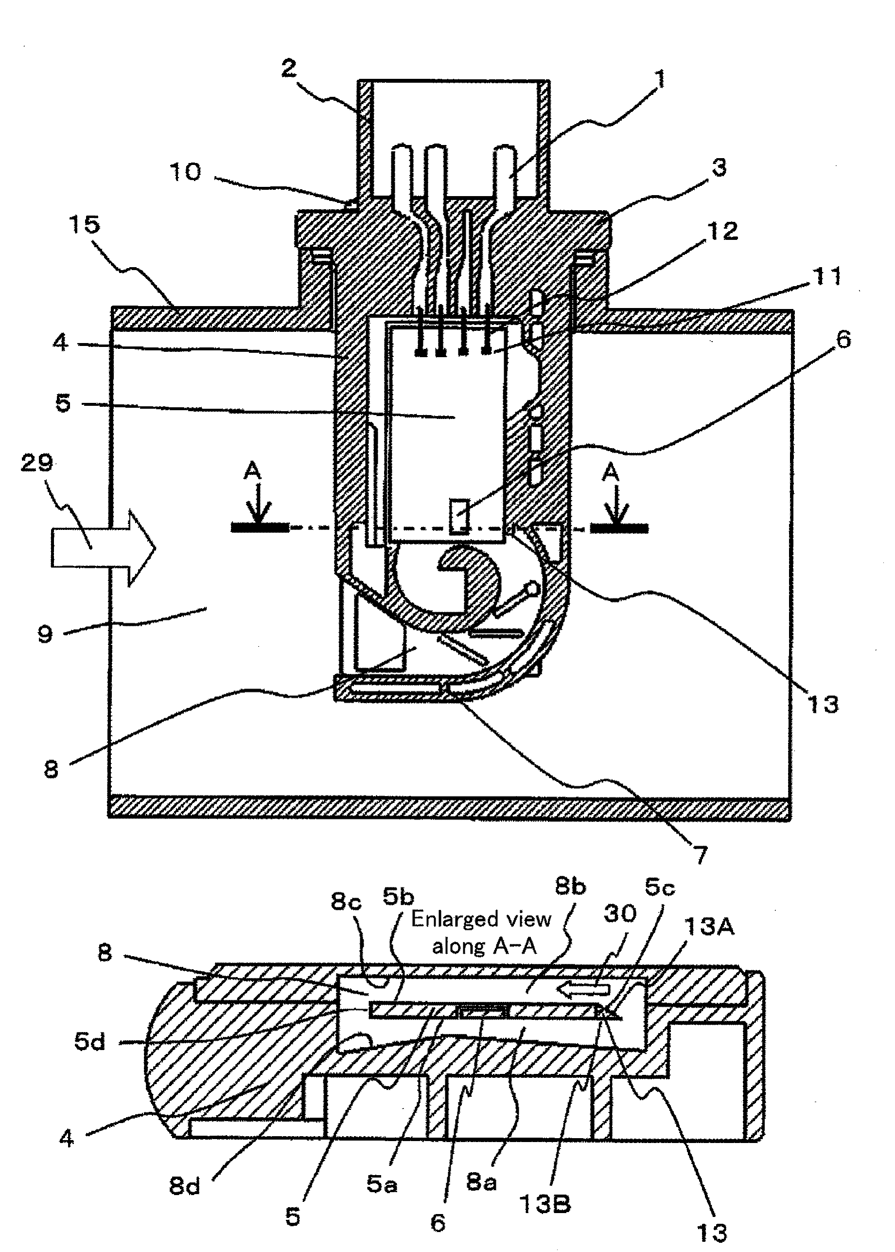
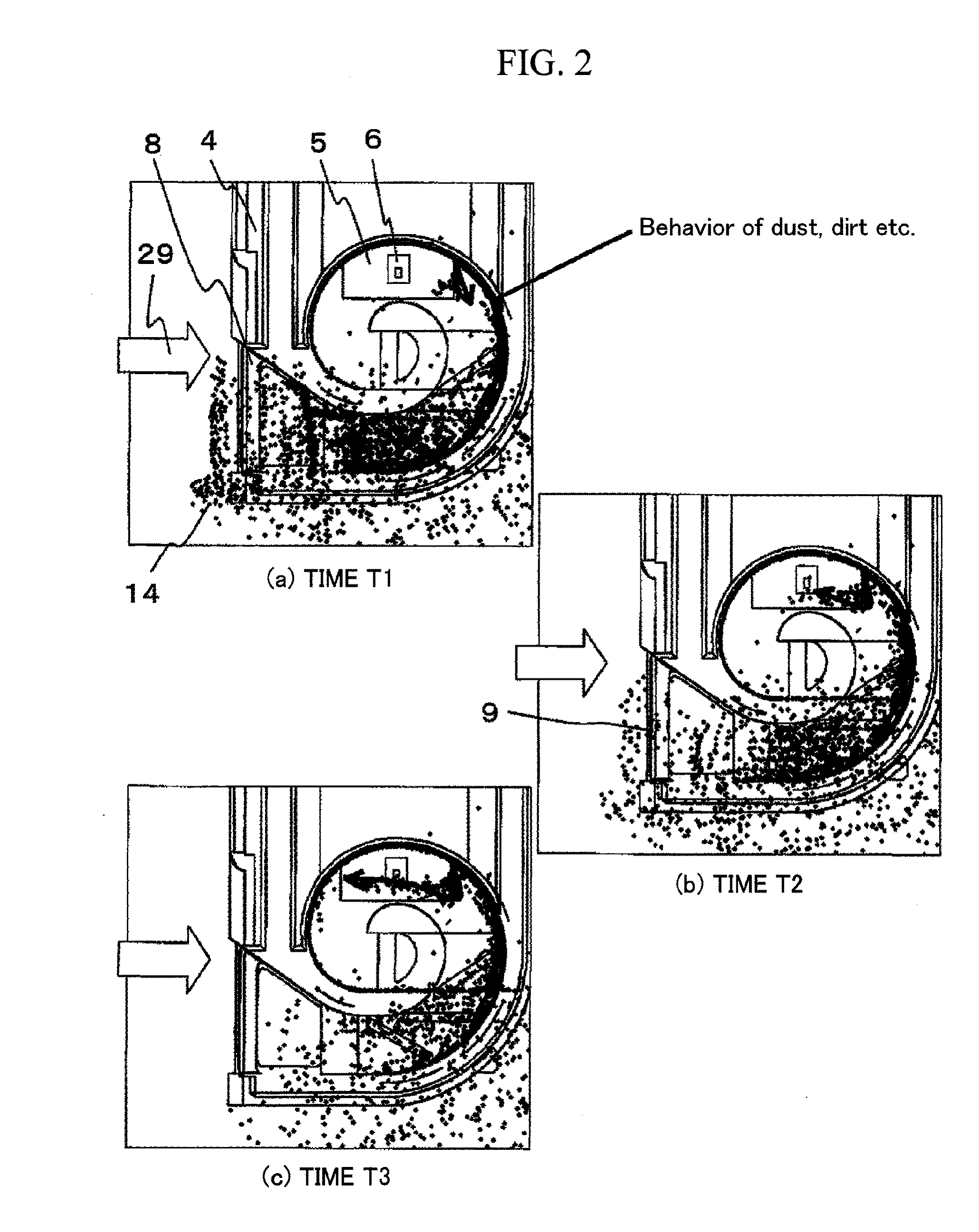
[0029]The following examples relating to the present invention relate to an air flow measuring instrument that is used for measuring the flow rate of air that is taken into an internal combustion engine for an automobile, and provide a structure that prevents damage to an air flow measuring element by contaminants such as dust that mix with air that is taken in and flow through the inside of an air intake duct, and also performs stable air flow rate measurement. In the following description, contaminants such as dust are referred to simply as “dust”.

[0030]Examples of the present invention will now be described specifically.

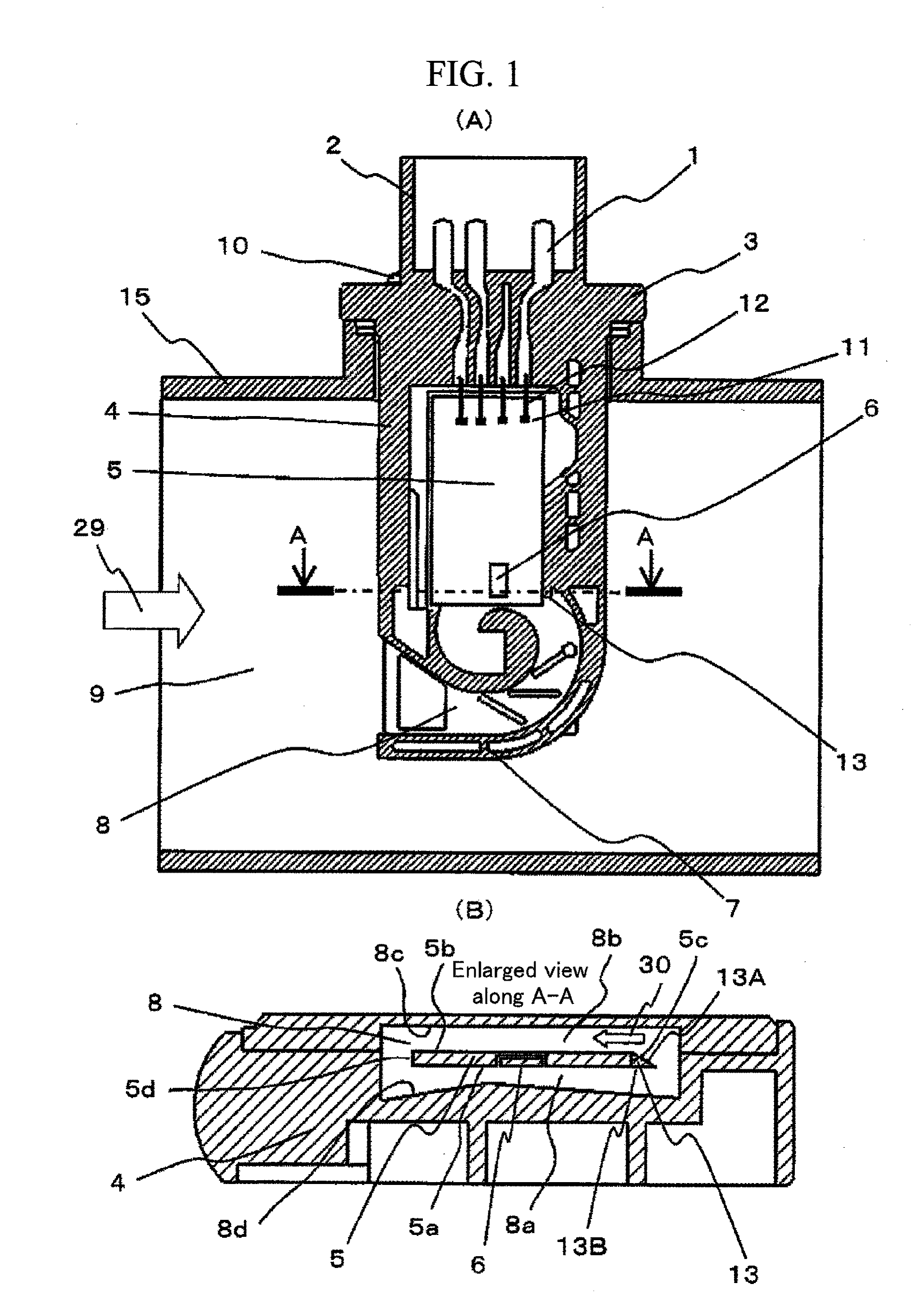
[0031]FIG. 1(A) is a front view of an air flow measuring instrument illustrating an example of the present invention, and FIG. 1(B) is an enlarged view of a cross section A-A thereof. The components of the present example will now be described referring FIG. 1.

[0032]A connector 2 having a connector terminal 1 for electrically connecting an electronic circuit 5 and...


PUM


Abstract

An air flow measuring instrument, comprising: an auxiliary passage 8 arranged inside a main passage through which fluid flows, a tabular member 5 on which a pattern of a heating resistor for measuring an air flow is provided on one face 5a, the tabular member being disposed inside the auxiliary passage so that the one face 5a on which the heating resistor pattern of the tabular member is provided is disposed along a flow of fluid inside the auxiliary passage 8, a heating resistor pattern-side fluid passage 8a portion formed so that the fluid flows between the face 5a and a passage-forming surface 8d of the auxiliary passage, and a back-surface 8b side fluid passage portion formed so that fluid flows between a face 5b on a side opposite to the face of the tabular member and the passage-forming surface of the auxiliary passage. Guidance portion 13 guiding dust that collides against the end portion to back-surface side fluid passage portion 8b side is provided on upstream-side end of tabular member.

Description

BACKGROUND OF THE INVENTION[0001]1. Field of the Invention[0002]The present invention relates to a flow meter, and more particularly to an air flow measuring instrument that comprises an intake system of an automobile engine and is suitable for detecting and controlling an air-intake amount.[0003]2. Background Art[0004]An instrument that measures a flow rate using the amount of heat discharge of a heating resistor obtained by carrying out heat control of the heating resistor, and an instrument that measures a flow rate by carrying out heat control of a heating resistor and measuring temperature changes in a temperature sensing resistor disposed adjacent to the heating resistor and the like are known as air flow measuring instruments that measure an air flow rate. The air flow measuring instrument is mounted in one part of an air intake duct of a vehicle, and fulfills the role of measuring the intake air flow rate. Normally, an air filter is provided in the air intake duct, and dust ...

Claims


Application Information

Patent Timeline
Patent Type & Authority Applications(United States)
IPC IPC(8): G01F1/69
CPCG01F1/6845G01F15/12G01F5/00
Inventor SAITO, NAOKIMORINO, TAKESHIOKAMOTO, YUKIHANZAWA, KEIJIKIKAWA, HIROMUYASUKAWA, AKIO
Owner HITACHI LTD
Why Eureka
Try Eureka