
Method of automatically adjusting the printing pressure in flexographic printing machines

a printing machine and printing technology, applied in printing, rotary presses, printing processes, etc., can solve the problems of large mechanical demands, complex analysis, and high printing pressure, and achieve the effect of saving waste of printed materials, simple analysis, and good print quality

Inactive Publication Date: 2009-05-21
COMEXI GRP IND
View PDF6 Cites 7 Cited by
  • Summary
  • Abstract
  • Description
  • Claims
  • Application Information

AI Technical Summary

Benefits of technology

[0007]It is necessary to provide an alternative to the state of the art by means of providing a method which makes it possible to control the pressure of the rollers of a flexographic machine so as to assure good print quality, but which does not suffer the drawbacks like the aforementioned background documents, which takes direct measurements of printed images in a simpler manner than in the last mentioned background document to detect the print quality, saves wastes of printed material, and it also provides a simpler analysis than the analysis carried out in the mentioned background document, which involves having to handle a much smaller amount of data than those necessary to carry out the method of the mentioned background document relating both to the captured images and to the recorded reference values indicative of good print quality.

Problems solved by technology

One drawback of said proposal is the need of providing a recess to house the mentioned sensor on the surface of the plate cylinder, which due to being located in such place will be subjected, along with the associated wiring, to considerable stress and / or mechanical demands, since the cylinder is in continuous movement.
Another disadvantage is that detecting the pressure of the plate cylinder is not a direct measurement of the quality of the printed image, since other factors in addition to pressure (such as a poor calibration or misfit of the cylinders) can affect said print quality.
If the comparison provides an unsatisfactory result, the control unit generates actuation signals to move one or more of said cylinders until the exerted pressure produces a good print quality.
Although said background document does propose an automatic and direct method of verifying the print quality, the necessary analysis is complex, if the quality is determined by means of a comparison of contrasts or of boundaries or of the reflected light intensity, since a large amount of data is necessary to carry out said comparisons, both in relation to the captured images and regarding the recorded information to be used as a reference.
Another drawback is that the image must be captured downstream of the printing area, which comprises a significant waste of print material.

Method used


Image

  • Method of automatically adjusting the printing pressure in flexographic printing machines
  • Method of automatically adjusting the printing pressure in flexographic printing machines
  • Method of automatically adjusting the printing pressure in flexographic printing machines

Examples


Embodiment Construction

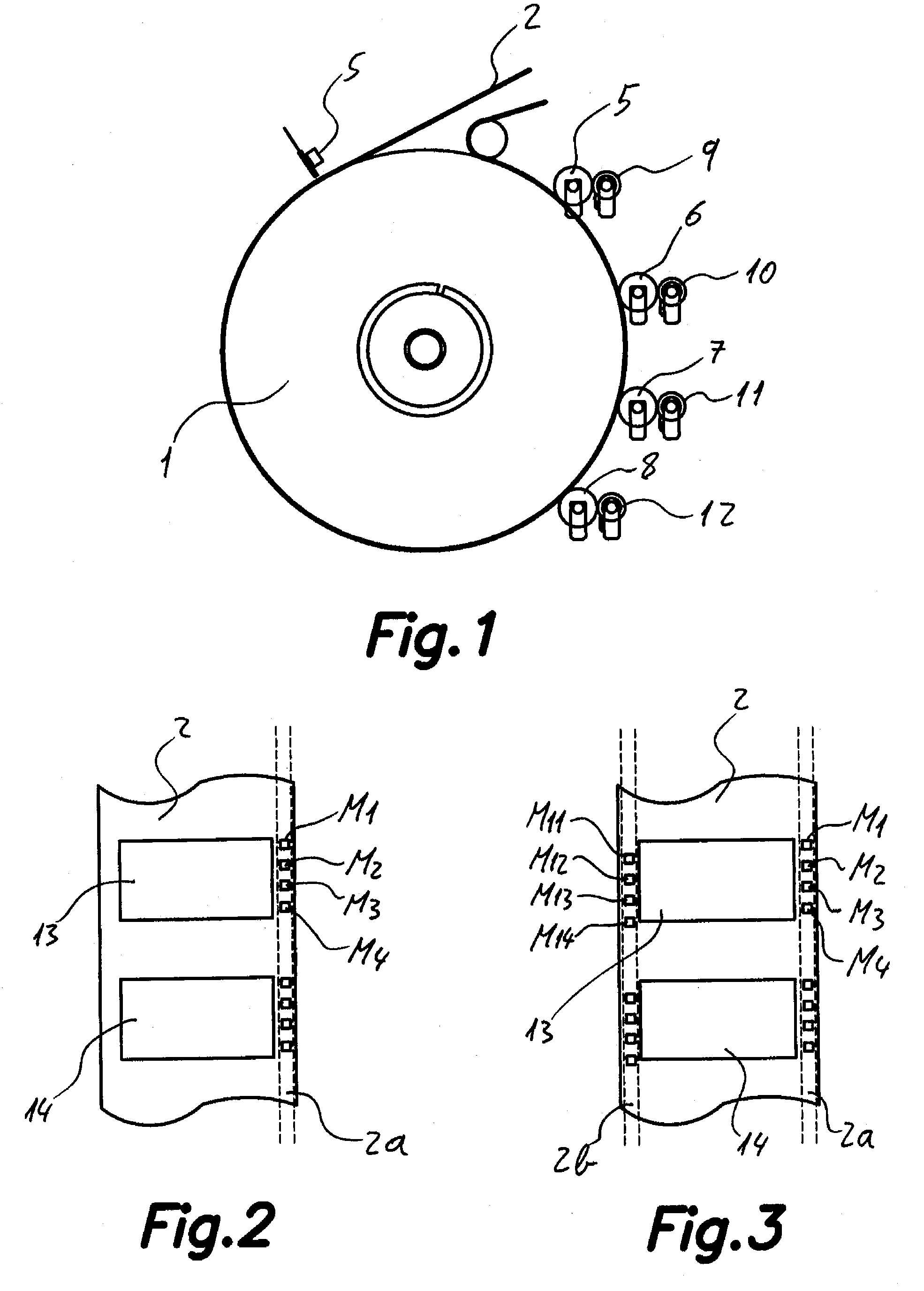
[0032]This invention relates to a method of automatically adjusting the printing pressure in flexographic printing machines (such as the one schematically shown in FIG. 1) with a rotating support drum 1 on which there is supported a laminar material 2 to be printed and a series of printing rollers 5, 6, 7, 8 each associated to a respective ink roller 9, 10, 11, 12, belonging to respective printing units, arranged around said support drum 1 and spaced along its perimeter (FIG. 1 only shows one sector, although there are generally printing units on both sides of the support drum 1).

[0033]The method is of the type comprising the following steps:

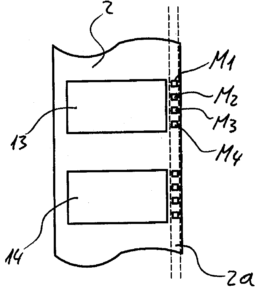
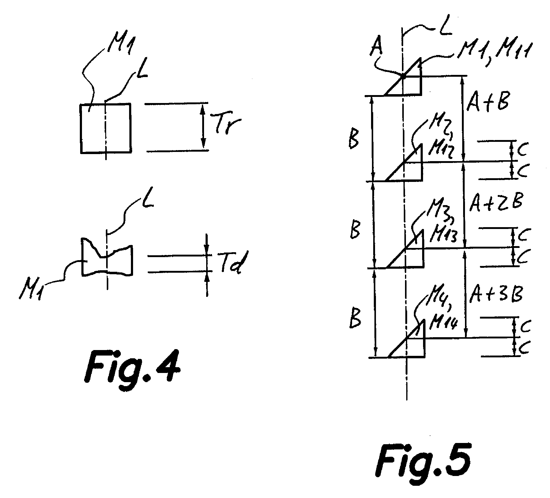
[0034]a) detecting a mark M1 (see FIGS. 2 to 5) printed with at least one 5 of said printing rollers 5, 6, 7, 8 and obtaining values representative of the size Td (see FIG. 4) of said detected mark M1 by carrying out the next sub-steps:[0035]a.1) detecting the start and the end of said mark M1 by means of a photoelectric sensor S (see FIG. 1) as...


PUM


Abstract

A method of automatically adjusting the printing pressure in flexographic printing machines is disclosed. The method is applied to flexographic machines with a rotating support drum around which a series of printing units with a series of printing rollers associated to respective ink rollers are arranged, and includes carrying out for each printing unit: detecting the start and the end of one mark (M1) printed with a printing roller and the angular positions of one or more rollers of the printing unit to which the printing roller belongs, and based on the detections establishing the size (Td) of the mark; comparing the detected size (Td) with a predetermined size (Tr) of the mark (M1) which is representative of a good print quality, and if the sizes are not equal adjusting the pressure of the printing roller which has printed the mark (M1) and of the associated ink roller.

Description

FIELD OF THE ART[0001]This invention generally relates to a method of automatically adjusting the printing pressure in flexographic printing machines by means of adjusting printing rollers and ink rollers belonging to a printing unit, and particularly to carrying out said adjustment according to the detection of the size of marks printed on a laminar material.PRIOR STATE OF THE ART[0002]In the state of the art there are different systems and methods of controlling the operation of flexographic printing machines for the purpose of obtaining high quality printings. One of the most important and influential parameters in print quality is none other than the pressure exerted between the different rollers responsible for said print in the moment it is carried out.[0003]A proposal aimed at controlling the mentioned printing pressure is described in patent document U.S. Pat. No. 5,967,034, relating to a method and a device for detecting and controlling the printing pressure applied to a fl...

Claims


Application Information

Patent Timeline
Patent Type & Authority Applications(United States)
IPC IPC(8): B41F1/34
CPCB41F13/24G06F3/1286B41P2200/11B41F33/0081B41F33/0072
Inventor PUIG VILA, JORDISAHUN PERES, JORDIFERRER CADILLACH, FELIP
Owner COMEXI GRP IND
Learn More