Compact beverage pressure regulator

a beverage pressure regulator and compact technology, applied in the direction of fluid pressure control, couplings, instruments, etc., can solve the problems of liquid spillage, liquid spillage, health hazards, etc., and achieve the effect of reducing hose connections, less hoses, and better pressure regulation

Active Publication Date: 2009-05-21
XYLEM IP HLDG
View PDF22 Cites 0 Cited by
  • Summary
  • Abstract
  • Description
  • Claims
  • Application Information

AI Technical Summary

Benefits of technology

[0018]Advantages of the present invention include eliminating the hose connection between the pump and pressure regulator that would otherwise be left to droop, be prone to breaking, make finding the right connections difficult for a mounted panel of such pumps, and result in undesirable liquid spills. The direct connection between the pressure regulator and pump also provides for better pressure regulation because there is less hose, while decreasing labor time when installing the configuration because there is no screwing / unscrewing of various parts, etc., which is being done in the prior art configuration. Moreover, according to some embodiments of the present invention, the new pressure regulator may be shorter by about 4 inches from known devices, which allows the regulator to stay within the known mounting panel and not protrude out, and therefore are much less likely to be broken or damaged. Furthermore, equipping both ends of the new pressure regulator with the quick disconnect devices allows multiple lines to stay organized so there is less likelihood of mistakes. Also, lines can be easily disconnected which will save time for services calls.

Problems solved by technology

This prior art configuration results in very long hose connections that droop, are prone to break, make finding the right connections difficult, result in liquid spills.
It is also difficult to keep multiple lines organized and this could cause confusion finding the right connections and a possible health hazard and liquid spills.
There may also be increased labor cost in configuring the same.

Method used


Image

  • Compact beverage pressure regulator
  • Compact beverage pressure regulator
  • Compact beverage pressure regulator

Examples


Embodiment Construction

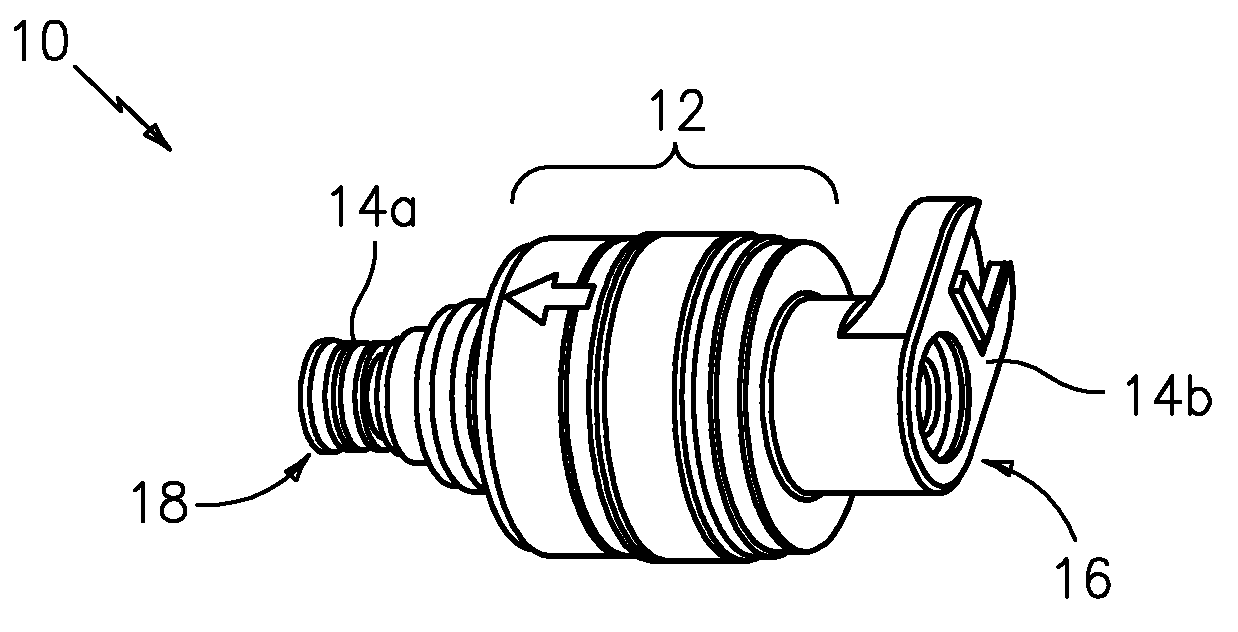
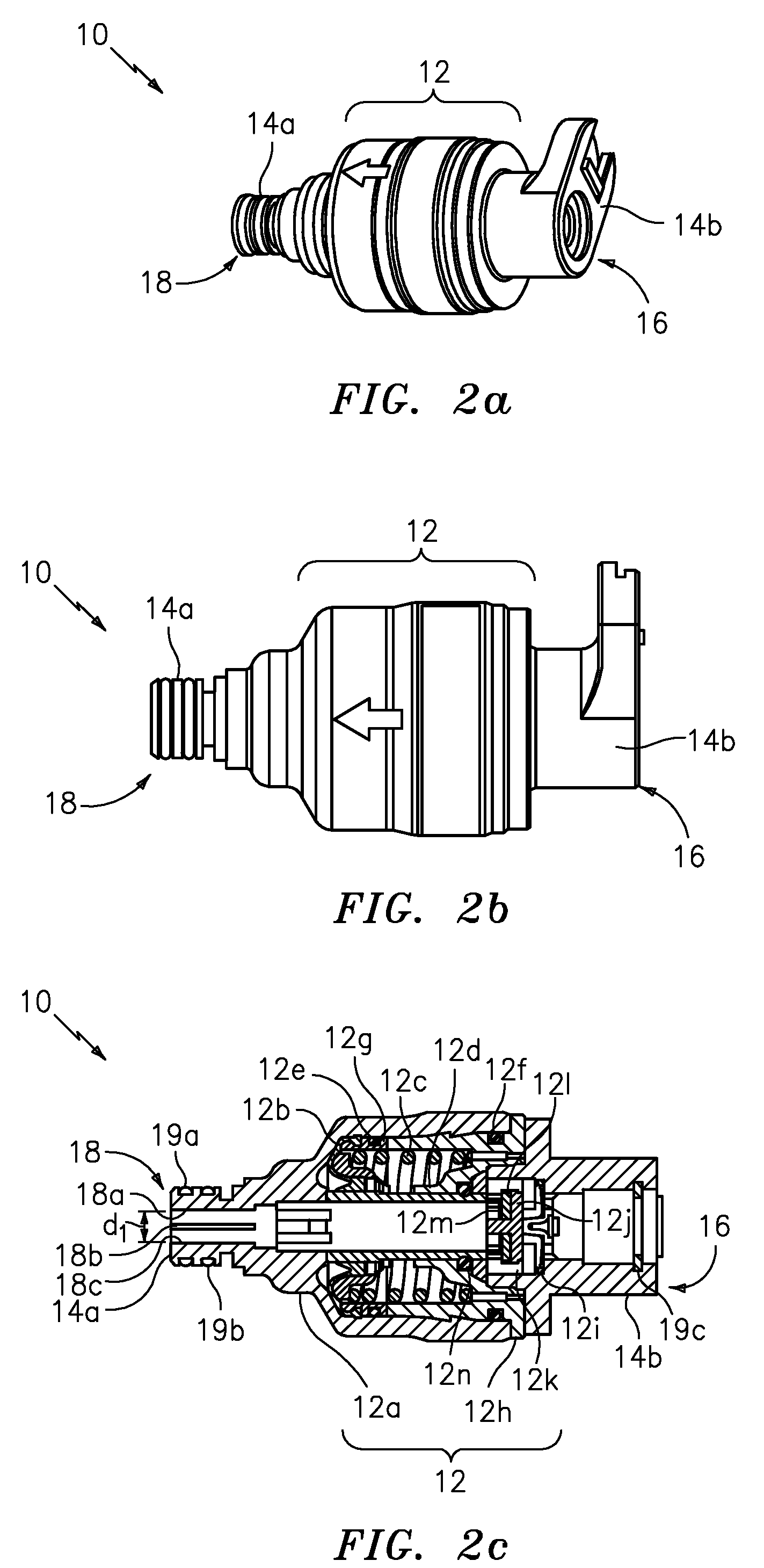
[0025]FIG. 2 shows a new and unique pressure regulator generally indicated as 10 featuring a body member 12 and one or more quick-disconnect devices 14a, 14b.

[0026]The body member12 regulates the pressure of a fluid flowing therein, has two ends generally indicated as 16 and 18, one end 16 for receiving the fluid and another end 18 for providing pressure regulated fluid.

[0027]The quick-disconnect device 14a (i.e. male) and / or 14b (i.e. female) are respectively arranged on ends 16 or 18 for coupling the body member 12 to a corresponding quick-disconnect device (not shown) that forms part of a device that either provides the fluid or receives the pressure regulated fluid. As shown in FIG. 3 or 4, the device may take the form of a pump for receiving the pressure regulated fluid.

[0028]By way of example, the pressure regulator 10 is shown having two quick-disconnect devices 14a, 14b, each quick-disconnect device being arranged on a respective end 16, 18 of the body member 12, although t...


PUM

PropertyMeasurementUnit
diameter d1aaaaaaaaaa
pressureaaaaaaaaaa
pressuresaaaaaaaaaa

Abstract

The present invention provides a new and unique pressure regulator featuring a body member for regulating the pressure of a fluid flowing therein, the body member having two ends, one end for receiving the fluid and another end for providing pressure regulated fluid; and a quick-disconnect device arranged on at least one end for coupling the body member to a corresponding quick-disconnect device that forms part of a device that either provides the fluid or receives the pressure regulated fluid. The pressure regulator may have two quick-disconnect devices, each quick-disconnect device being arranged on a respective end of the body member. The quick-disconnect device may include a male quick-disconnect device for coupling to a corresponding female quick-disconnect device that forms part of either a hose or a dispenser for providing the fluid or a pump for receiving the pressure regulated fluid; or a female quick-disconnect device for coupling to a corresponding male quick-disconnect device that forms part of either a hose or a dispenser for providing the fluid or a pump for receiving the pressure regulated fluid. The present invention may also include a method for coupling such a quick-disconnect device of such a pressure regulator to such a corresponding quick-disconnect device of a pump for providing fluid flow, as well as a combination of such a pressure regulator and such a pump for providing fluid flow.

Description

BACKGROUND OF THE INVENTION[0001]1. Field of the Invention[0002]The present invention relates to a method and apparatus for regulating the pressure in order to control the flow of a fluid, such as water / syrup.[0003]2. Brief Description of Related Art[0004]There are known pressure regulators that are mainly used to control water or beverage syrup flow in various pressures ranging from 15 PSI to 40 PSI. The devices typically consist of a body member with internal components to control pressure, i.e. springs, rubber membranes, restrictors, Etc. Both ends usually have a hose connection or a hose barb fitting. Water or syrup flow is controlled to the desired flow with a matching internal spring.[0005]For example, FIG. 1 shows one such known pressure regulator having an inner regulator portion and a male end portion on each side. The left end portion as shown has a first fitting welded to the inner regulator portion, a second fitting screwed into the first fitting, and a third hose barb f...

Claims


Application Information

Patent Timeline
Patent Type & Authority Applications(United States)
IPC IPC(8): F16L37/00F16K15/00G05D16/04F16K17/00
CPCF16K1/123G05D16/0655F16L37/088G05D16/0608Y10T137/0396Y10T137/86002Y10T137/88054
Inventor REITTER, KLAUSCALDWELL, GERARD K.BYRD, JON
Owner XYLEM IP HLDG
Why Eureka
Try Eureka