Valve, in particular for compressors

a compressor and valve body technology, applied in the field of valves, can solve the problems of high opening/closing frequency, increase in the reliability problems of the abovementioned components, wear of varying nature and varying degrees, etc., and achieve the effect of preserving the wear of the components

Inactive Publication Date: 2009-05-21
DOTT ING MARIO COZZANI S R I
View PDF7 Cites 0 Cited by
  • Summary
  • Abstract
  • Description
  • Claims
  • Application Information

AI Technical Summary

Benefits of technology

[0012]In a preferred embodiment, the end turns both have dimensions smaller than those of the immediately adjacent turns. Advantageously, the valve according to the present invention may be provided with protection members which are preferably made of plastic material and are arranged inside the housing which accommodates the spring, so as to preserve further the wear thereof.

Problems solved by technology

The springs constitute one of the most critical parts of the valve; in fact, the high opening / closing frequencies produce, on them and on the parts in contact with them, wear of varying nature and varying degrees.
Despite these improvements, the spring continues to be one of the most critical parts of the valve and the cause of malfunctions.
The development of increasingly faster compressors and the continuous efforts to eliminate the oil in the compressed gas have resulted in an increase in the problems of reliability of the abovementioned components.

Method used


Image

  • Valve, in particular for compressors
  • Valve, in particular for compressors
  • Valve, in particular for compressors

Examples


Embodiment Construction

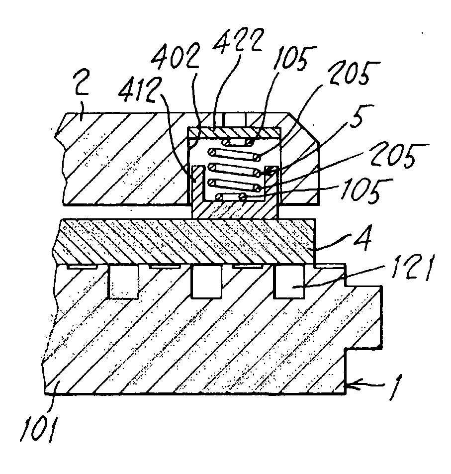
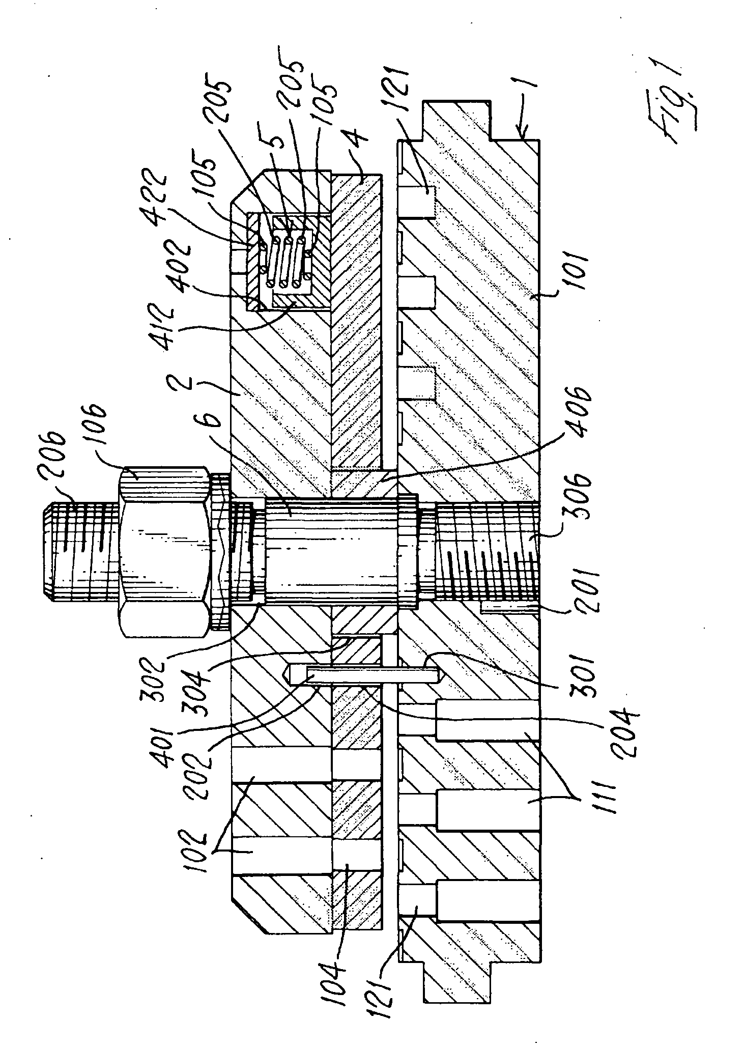
[0018]FIG. 1 shows an embodiment of the valve according to the present invention; 1 denotes the seat of the said valve, comprising a plate 101 provided with a plurality of axial and eccentric through-holes 111 acting as flow ways for the fluid and having a central, axial, threaded, through-hole 201 with which the threaded end 306 of the bolt 6 mates. The plate 101 also has formed therein the grooves 121 which communicate with the through-holes 111. The central portion of the bolt 6 also has, mounted thereon, the bush 406 and the counter-seat 2 provided with a central axial through-hole 302; the seat 1, bush 406 and counter-seat 2 are fixed together by means of the nut 106 screwed onto the threaded end 206 of the bolt 6. The axial through-ducts 102 are formed in the counter-seat 2.

[0019]The obturator 4 is arranged between the seat 1 and the counter-seat 2, being coaxial and concentric with the bush 406 and axially slidable along it by means of its central axial hole 304. The obturato...


PUM


Abstract

Valve, in particular for compressors, comprising a seat (1) provided with at least one flow way (111), an obturator member (4) able to obstruct said flow way (111) and movable with respect to said seat in a given direction, and means (5) for resiliently stressing said obturator (4), which are able to force said obturator (4) into a given position and are active in the direction of movement thereof; said resilient stressing means (5) comprise at least one cylindrical helical compression spring (5), characterized by the presence, between all the turns and along the entire working length of the spring (5), of inter-turn apertures.

Description

BACKGROUND AND SUMMARY OF THE INVENTION[0001]The present invention relates to a valve, and in particular relates to a valve for reciprocating compressors of the reciprocating type.[0002]The valves of the type currently used in said compressors are normally automatic valves, comprising a valve body, called the seat, consisting of a plate having, formed therein, a plurality of axial flow channels which may be concentric or non-concentric. The opening and closing of said channels is performed by the obturator, a member which may consist of a plurality of elements or a single element. In all cases the obturators are subject to the action of resilient stressing means, typically metal, cylindrical helical, compression springs. The springs are housed inside a valve body (called “counter-seat”) consisting of a plate in which the flow through channels are formed. The abovementioned spring housings may also contain spring protection elements which are preferably made of thermoplastic material...

Claims


Application Information

Patent Timeline
Patent Type & Authority Applications(United States)
IPC IPC(8): F16K15/00
CPCF04B39/102F04B39/1066F04B39/1033Y10T137/7922F04B39/10
Inventor SCHIAVONE, MASSIMO
Owner DOTT ING MARIO COZZANI S R I
Why Eureka
Try Eureka