Friction Clutch and Vehicle Equipped with the Same

a friction clutch and clutch technology, applied in the direction of fluid actuated clutches, clutches, non-mechanical actuated clutches, etc., can solve the problems of increasing the load required to operate the clutch, affecting the operational burden of the rider, and complicating in turn the overall structure of the clutch, so as to simplify the outer shape requirements, reduce the operational load needed to disengage the clutch, and simplify the effect of the friction clutch structur

Inactive Publication Date: 2009-05-21
YAMAHA MOTOR CO LTD
View PDF2 Cites 13 Cited by
  • Summary
  • Abstract
  • Description
  • Claims
  • Application Information

AI Technical Summary

Benefits of technology

[0013]Further, in the friction clutch of the present invention, the friction plate is arranged to rotate together with the pressure plate. The pressure plate is supported on the drive side rotating body so as to be movable in an axial direction with respect to the drive side rotating body and rotate together with the drive side rotating body. The drive side rotating body is configured to rotate in response to rotation of the crankshaft of an engine. Therefore, in the friction clutch according to the present invention, rotation of the crankshaft of the engine is transmitted to the friction plate solely through the drive side rotating body and the pressure plate. Consequently, the friction clutch of the present invention advantageously simplifies the outer shape requirements for the pressure plate and the friction plate when a transmission path is constituted between the pressure plate and the sub clutch.
[0014]Therefore, the friction clutch structure can be simplified and the operational load needed to disengage the clutch can be decreased in accordance with the present invention.

Problems solved by technology

This, however, increases the load required to operate the clutch, which in turn impacts the operational burden on the rider.
Therefore, in constituting a transmission path between the pressure plate and the sub clutch, the outer shape requirements for the pressure plate and the pressing member become relatively complicated which complicates in turn the overall structure of the clutch.

Method used


Image

  • Friction Clutch and Vehicle Equipped with the Same
  • Friction Clutch and Vehicle Equipped with the Same
  • Friction Clutch and Vehicle Equipped with the Same

Examples


first embodiment

Modification of First Embodiment

[0106]According to the above-described embodiment, in the idling state in which the rotational speed of the crankshaft is low, the clutch is set to a state in which the pressure plate 77 does not press the plate group 66 into contact with each other; that is, the clutch is in a disengaged state at a low speed such as an idling speed. However, the biasing force applied by the disc spring 83 and the coil spring 205 may be adjusted such that even in the idling state or the like in which the rotational speed is low, the clutch can be set to a state in which the pressure plate 77 presses the plate group 66 into frictional contact. In other words, the biasing force may be adjusted such that the clutch can be set to a so-called partially-applied clutch state.

second embodiment

Configuration of Clutch

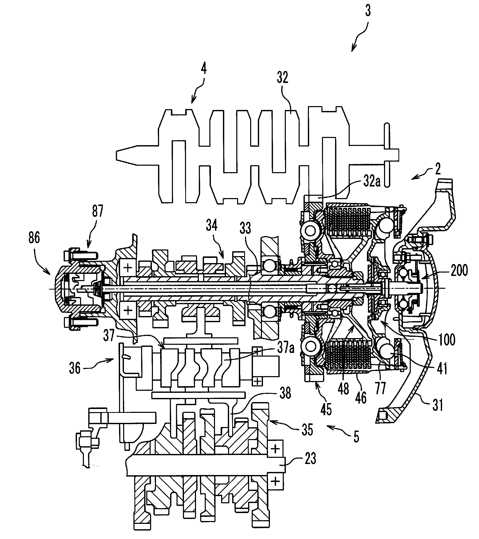
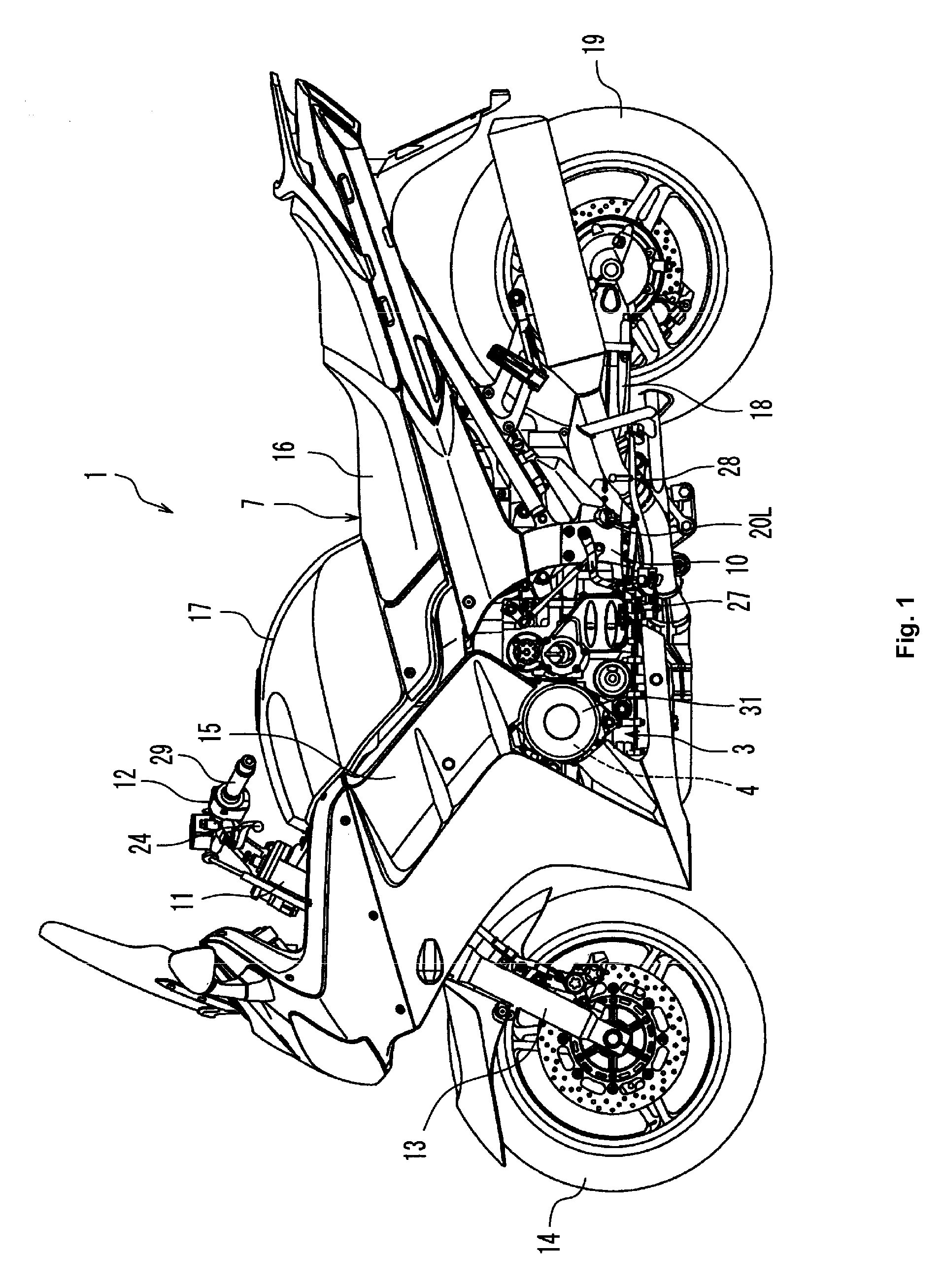
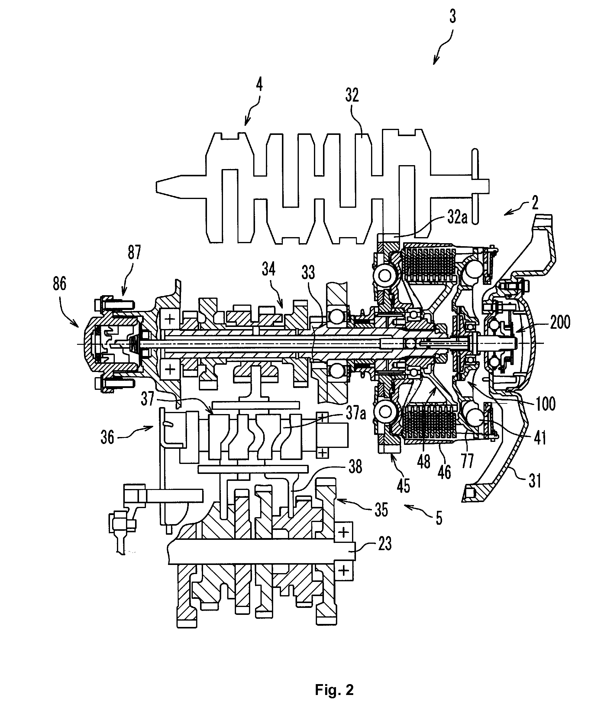
[0107]A clutch 2 according to a second embodiment comprises a wet multi-plate type friction clutch. The clutch 2 according to the present embodiment is engaged / disengaged by a clutch lever 24 (FIG. 1) operated by a rider. However, the clutch 2 according to the present embodiment does not include a roller weight, such as roller weights 41 shown in FIG. 3 and described in reference to the first embodiment of the present invention.

[0108]The configuration of a clutch 2 according to the second embodiment will be described below in detail with reference to FIGS. 6, 7a, 7b, and 7c. In the first and second embodiments, like reference numerals denote like components, and thus duplicated description will not be repeated.

Pressure Plate 77

[0109]As shown in FIG. 6, a pressure plate 77 is disposed on the right side of the main shaft 33. The pressure plate 77 has a substantially disc-like shape. A sub clutch 100, which will be described later, is provided adjacent a central ...


PUM


Abstract

A friction clutch includes a clutch housing having a friction plate, a clutch boss having a clutch plate, a pressure plate, a sub clutch, and a power-assist mechanism. An elastic member urges the pressure plate in a predetermined direction to press the friction plate and the clutch plate into frictional contact with each other when the clutch is engaged. The sub clutch includes a friction plate operatively disposed between first and second pressing plates. The power-assist mechanism receives torque from the pressure plate via the sub clutch when the clutch is disengaged and converts the torque into a force for moving the pressure plate in a direction which separates the pressure plate from a plate group.

Description

PRIORITY INFORMATION[0001]This patent application is based on and claims priority under 35 U.S.C. § 119 to Japanese Patent Application No. 2007-301716, filed on Nov. 21, 2007, and Japanese Patent Application No. 2008-264597, filed on Oct. 10, 2008, the entire contents of which are hereby expressly incorporated by reference.TECHNICAL FIELD[0002]The present invention relates to a friction clutch and a vehicle equipped with the same.BACKGROUND ART[0003]Vehicles equipped with a friction clutch for engaging / disengaging the transmission of an engine drive force and a device for operating the friction clutch are well known. An example of a device used to operate a clutch is a clutch lever of a motorcycle.[0004]Generally, as the size of a vehicle becomes larger, the capacity of the friction clutch becomes larger, and the force necessary to disengage the friction clutch also becomes larger. This, however, increases the load required to operate the clutch, which in turn impacts the operationa...

Claims


Application Information

Patent Timeline
Patent Type & Authority Applications(United States)
IPC IPC(8): F16D13/28
CPCF16D13/04F16D25/02F16D43/12F16D13/54
Inventor INOMORI, TOSHINORIISHIDA, YOUSUKE
Owner YAMAHA MOTOR CO LTD
Why Eureka
Try Eureka