Double-functional rolling blade wheel group and multi-functional shredder

a multi-functional, shredder technology, applied in the direction of grain treatment, cocoa, agriculture, etc., can solve the problems of reducing the lifespan of the shredder, neglecting other performance of the shredder, and imbalance of the shredder, so as to achieve balanced power, optimize the inner space, and small size

Inactive Publication Date: 2009-05-21
GUANGZHOU COMET
View PDF9 Cites 4 Cited by
  • Summary
  • Abstract
  • Description
  • Claims
  • Application Information

AI Technical Summary

Benefits of technology

[0021]Compared with conventional shredders, the shredders of the present invention have small size, balanced po...

Problems solved by technology

However, in this kind of shredder, the functions of shredding paper documents and the rigid/semi-rigid objects are specially emphasized, while other performances of the shredders are neglected.
However, in the shredder as previously mentioned, evenly distributing power cannot be realized, which will lead to imbalance of the shredder.
Consequently, during operation of the shredder, the power imbalance causes barycenter imbalance and unstable running of the shredder, which will inevitably decreases the lifespan of the shredder.
However, on one hand, rigidity of the rolling blad...

Method used


Image

  • Double-functional rolling blade wheel group and multi-functional shredder
  • Double-functional rolling blade wheel group and multi-functional shredder
  • Double-functional rolling blade wheel group and multi-functional shredder

Examples


first embodiment

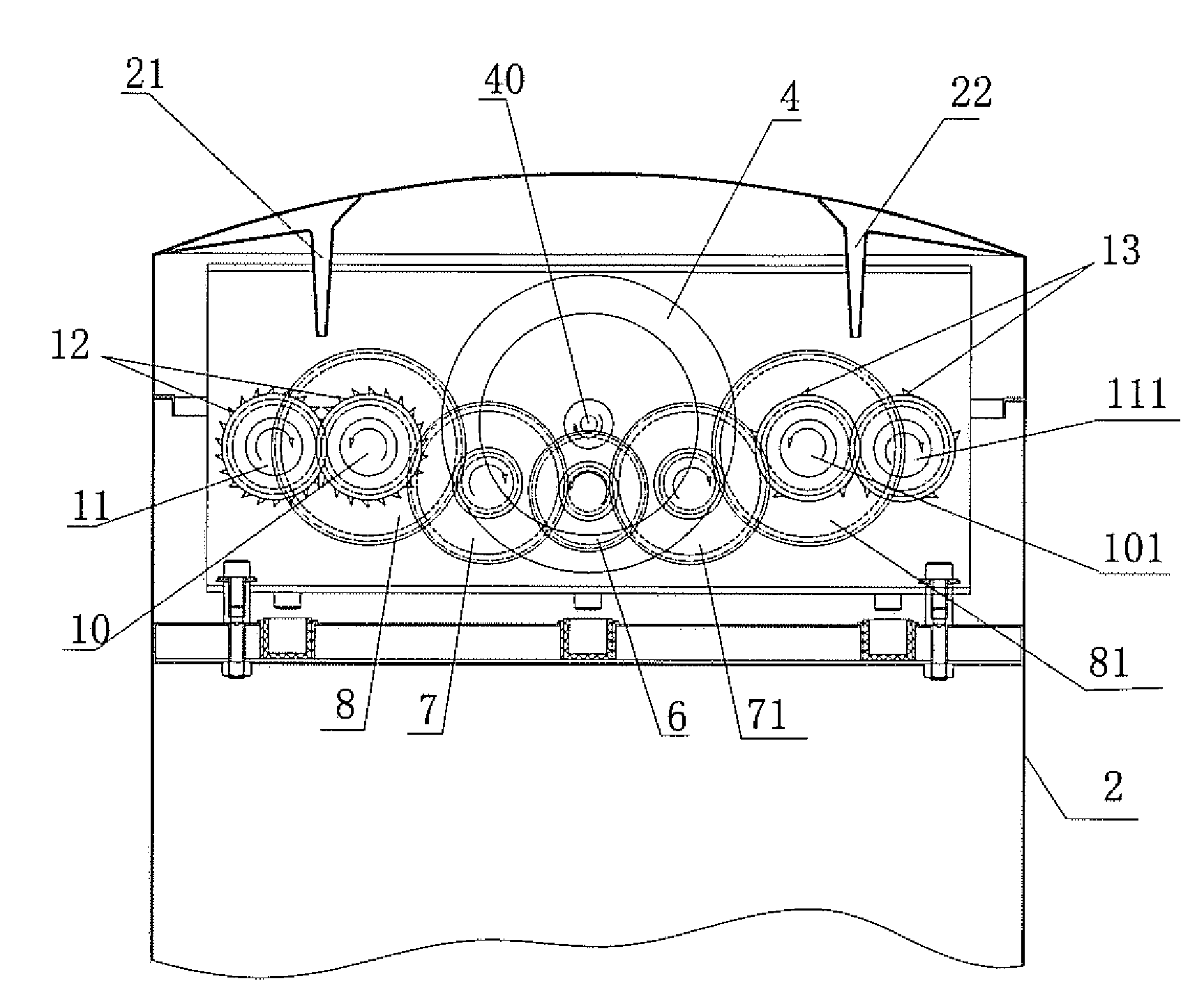
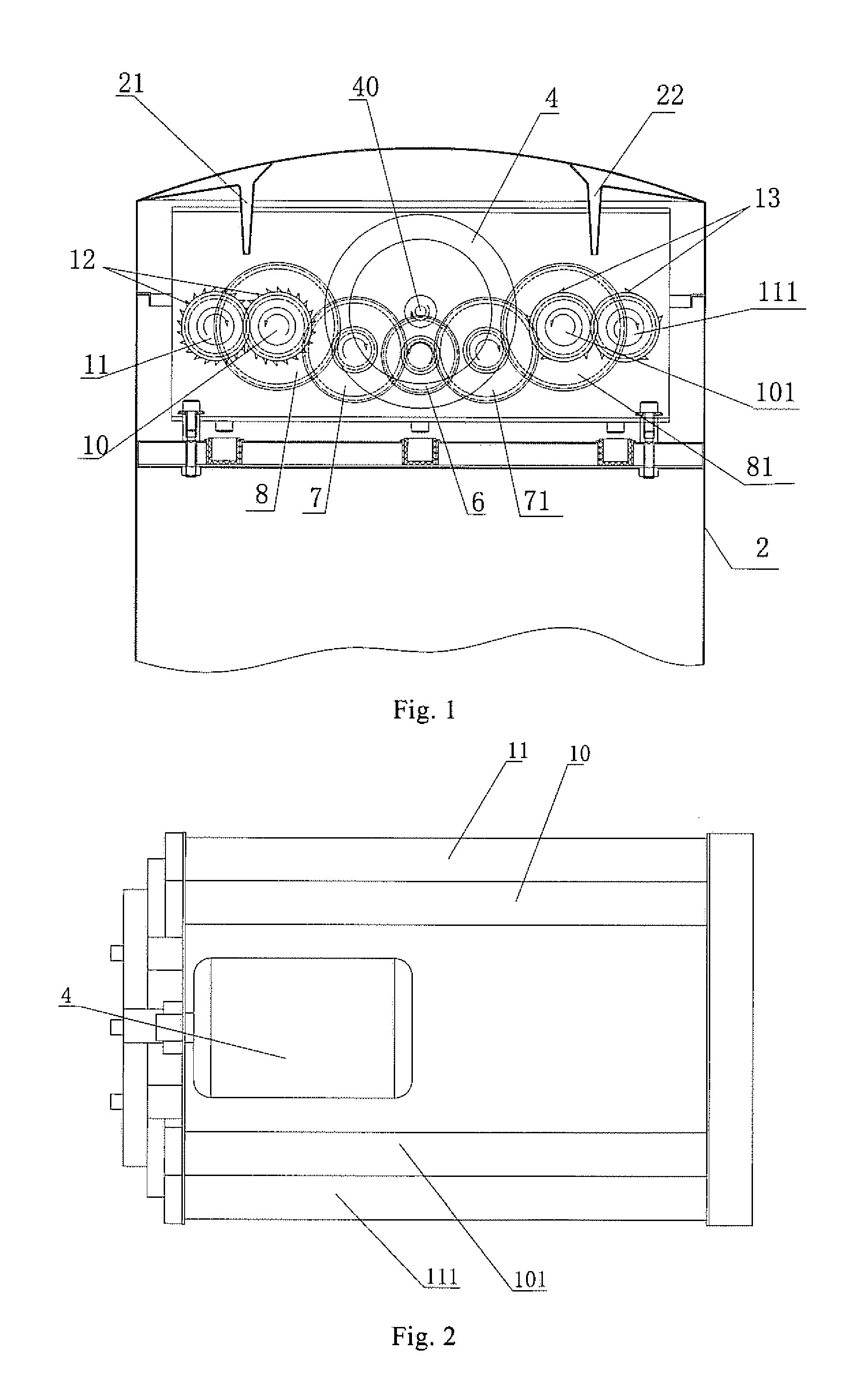
[0033]Referring to FIGS. 1 and 2, FIG. 1 depicts a plane view of a part of a shredder in accordance with the present invention, illustrating a shredding mechanism and a shell 2 for housing the shredding mechanism.

[0034]The shredding mechanism generally includes a motor 4, a first rolling blade wheel group 10, 11, a second rolling blade group 101, 111, a main gear 6, a first driving mechanism 7, 8, and a second driving mechanism 71, 81.

[0035]Referring particularly to FIG. 2, the first driving mechanism 7, 8 and the second driving mechanism 71, 81 are arranged symmetrically with respect to the main gear 6. The motor 4 drives the main gear 6 via an output axis 40 thereof. The motor 4 is disposed between the first driving mechanism 7, 8 and the second driving mechanism 71, 81 and, also, disposed between the first rolling blade wheel group 10, 11 and the second rolling blade wheel group 101, 111.

[0036]The first driving mechanism 7, 8 includes a first passive gear 8 and a first connecting...

second embodiment

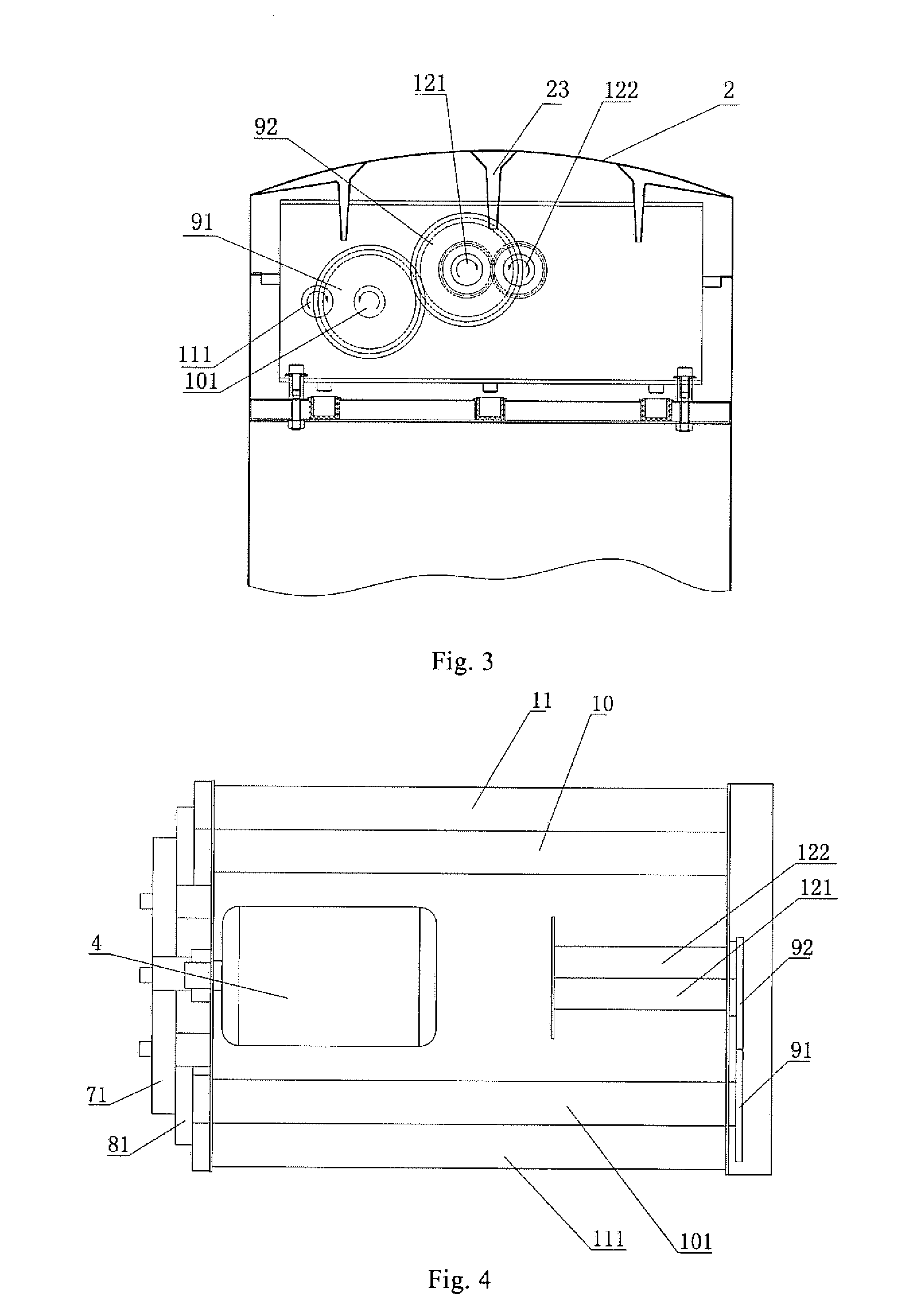
[0050]Referring to FIGS. 3 and 4, in the second embodiment, the third rolling blade wheel group 121, 122 synchronously rotates with the second rolling blade wheel group 101, 111 to perform shredding. It is understood that, if the third driving mechanism 91, 92 connects the third rolling blade wheel group 121, 122 with the first rolling blade wheel group 10, 11, the third rolling blade wheel group. 121, 122 can synchronously rotate with the first rolling blade wheel group 10, 11.

[0051]Relatively, with reasonable inner space, the shredder according to the second embodiment presents an advantage over the shredder of the first embodiment. That is to say, with the first rolling blade wheel group 10, 11 being used to chop paper documents, the third rolling blade wheel group 121, 122 can be used to chop compact discs. When one of the first and third rolling blade wheel groups 10, 11, 121, 122 is out of work, the second rolling blade wheel group 101, 111 could be used to chop paper document...

fifth embodiment

[0059]Referring to FIG. 9, a shredder in accordance with the present invention is improved from the shredder in FIG. 8. Two motors 4, 4′ are utilized to replace the motor 4 with two output axes in FIG. 8. The driving mechanisms 678, 678′ are remained. The rolling blade wheel groups 188, 188′ are disposed in a middle portion with the rolling blade wheel groups 188, 188′ connecting with the driving mechanisms 678, 678′ respectively. The motors 4, 4′ are disposed at two outer sides of the rolling blade wheel groups 188, 188′. Consequently, synchronous rotations of the rolling blade wheel groups 188, 188′ are realized. Additionally, one of the rolling blade wheel groups 188, 188′ could also be configured as a double-functional rolling blade wheel group. A feeding opening is correspondingly defined in the shell (not shown in FIG. 9), thereby obtaining a multi-functional shredder.

[0060]In view of the above descriptions, the shredding mechanism according to the present invention overcomes ...


PUM


Abstract

The present invention provides a double-functional rolling blade wheel group having two rolling blade wheels. Each of the rolling blade wheels includes a number of rolling blades arranged in a longitudinal direction thereof. The rolling blades of one rolling blade wheel cooperate with the rolling blades on the other rolling blade wheel, so as to shred objects. Each of the rolling blade wheels forms at least two shredding areas along the longitudinal direction thereof. The number of blade rows along a circumference direction of one shredding area and the number of the rolling blades in each blade row along the longitudinal direction of the shredding area are different from those formed on the other shredding area.

Description

CROSS REFERENCE TO RELATED APPLICATIONS[0001]The present invention claims priority to Chinese Patent Application No. CN 200720059829.4 filed Nov. 20, 2007, which is incorporated by reference herein in its entirety.FIELD OF THE INVENTION[0002]The present invention relates to multi-functional shredders and a rolling blade wheel group for use in the multi-functional shredders.BACKGROUND OF THE INVENTION[0003]Conventionally, a paper shredding mechanism used in a shredder includes two rolling blade wheels parallel and adjacent to each other. Each of the rolling blade wheels each is provided with a number of rolling blades on the columnar surface thereof. One rolling blade wheel actuates the other rolling blade wheel via a gear mechanism. The rolling blades on one rolling blade wheel are staggered to and match to the rolling blades formed on the other rolling blade wheel, thereby forming a shearing and cutting effect to chop papers or other objects.[0004]Currently, shredders with double f...

Claims


Application Information

Patent Timeline
IPC IPC(8): B02C1/08
CPCB02C18/0007B02C2018/164B02C2018/0038
Inventor ZHONG, FENGQIANG
Owner GUANGZHOU COMET
Why Eureka
Try Eureka