Compound-eye imaging apparatus

a compound eye and imaging apparatus technology, applied in the field of compound eye imaging apparatus, can solve the problems of poor resolution compared with the usual single eye imaging apparatus, and affecting the image quality of the subj

Inactive Publication Date: 2009-05-21
PANASONIC CORP
View PDF10 Cites 88 Cited by
  • Summary
  • Abstract
  • Description
  • Claims
  • Application Information

AI Technical Summary

Benefits of technology

[0017]In accordance with the present invention, the shifted pixel arrangement can be achieved in a direction perpendicular to a direction in which the pixels are arranged. The subject distan

Problems solved by technology

In many cases, the reduction in size is obstructed by the size and focal length of an imaging optical lens and the size of an imaging device.
In general, since the refractive index of a material varies depending on the wavelength of light, it is difficult to form an image of light from

Method used


Image

  • Compound-eye imaging apparatus
  • Compound-eye imaging apparatus
  • Compound-eye imaging apparatus

Examples


embodiment 1

[0070]A compound-eye imaging apparatus according to the present embodiment improves vertical and horizontal spatial sampling characteristics compared with a conventional compound-eye imaging apparatus.

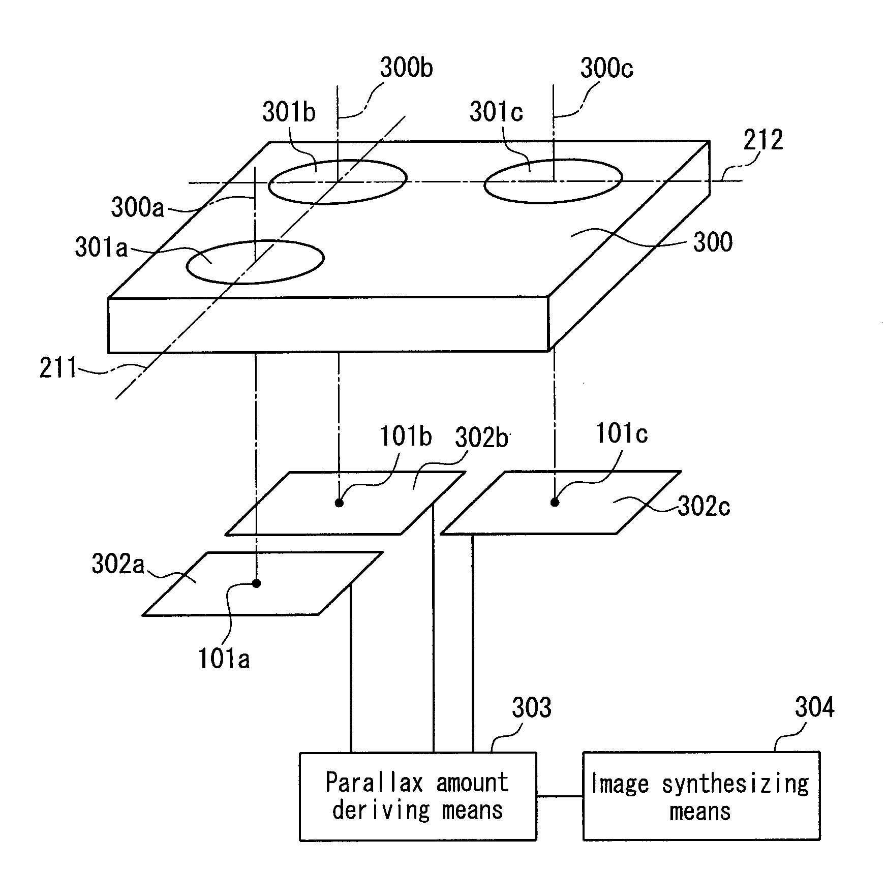
[0071]FIG. 1 is a perspective view showing an example of the compound-eye imaging apparatus according to Embodiment 1. Numeral 300 denotes a lens array formed of a transparent resin and including three lenses 301a, 301b and 301c that are integrally-formed. Optical axes 300a, 300b and 300c of the three lenses 301a, 301b and 301c are parallel with each other. The three lenses 301a, 301b and 301c are arranged in substantially the same plane so that, when viewed along a direction parallel with these optical axes, a first straight line 211 connecting the optical axes 300a and 300b and a second straight line 212 connecting the optical axes 300b and 300c form a right angle. The lenses 301a, 301b and 301c form subject images on imaging regions 302a, 302b and 302c, respectively. The imaging reg...

example 1

[0093]The following is a description of an example corresponding to Embodiment 1.

[0094]FIG. 6A is a plan view showing an imaging apparatus according to Example 1 viewed along a direction parallel with optical axes, and FIG. 6B is a sectional view thereof taken along a line 6B-6B in FIG. 6A. Numeral 700 denotes a lens array having three lenses that are integrally-formed using an acrylic resin. As shown in FIG. 6A, the three lenses were arranged so that their optical axes were located at three vertices of a square whose one side d was 2 mm long. All of the lenses were designed so that their optical characteristics were optimal with respect to green wavelength light. In the Z-axis direction, the distance from the lens center to the image forming plane was 2.5 mm. The lens array 700 was held by a cylindrical barrel 701. A surface of the barrel 701 facing the subject was provided with three apertures 702 corresponding to the positions of the lenses. A portion of a base 703 to be fitted w...

embodiment 2

[0100]Embodiment 1 has described the imaging apparatus using the lens array 300 including the three lenses 301a, 301b and 303c that are integrally-formed without any error in their relative positional relationship. However, if any forming error occurs in the relative positional relationship between a plurality of the lenses in an actual production of the lens array, it is difficult to correct. Thus, the lens array has to be formed at an accuracy finer than the pixel pitch in the imaging region, requiring a very high forming accuracy, so that a low-cost mass-production might become difficult.

[0101]On the other hand, it indeed is possible to prepare plural lenses separately and assemble these plural lenses while making a fine adjustment to the positional relationship with the corresponding plural imaging regions so that a desired shifted pixel arrangement is achieved, but this involves many adjusting processes and is not suitable for mass-production.

[0102]Embodiment 2 provides an imag...


PUM


Abstract

A plurality of imaging optical lenses (301a to 301c) form a plurality of subject images on a plurality of imaging regions (302a to 302c), respectively. When viewed along a direction parallel with optical axes, at least one straight line connecting corresponding points in at least one pair of the subject images that are formed by at least one pair of the imaging optical lenses is inclined with respect to a direction in which pixels are arranged in the imaging regions. In this way, a high-resolution image always can be obtained regardless of the subject distance.

Description

TECHNICAL FIELD[0001]The present invention relates to a compound-eye imaging apparatus that captures an image with a plurality of imaging optical lenses arranged substantially in the same plane.BACKGROUND ART[0002]Imaging apparatuses used in mobile equipment need to have both a high resolution and a small size. In many cases, the reduction in size is obstructed by the size and focal length of an imaging optical lens and the size of an imaging device.[0003]In general, since the refractive index of a material varies depending on the wavelength of light, it is difficult to form an image of light from a subject including information of an entire wavelength range on an imaging plane using a single lens. Therefore, in an optical system of usual imaging apparatuses, a plurality of lenses are arranged along an optical axis direction so that images of red wavelength light, green wavelength light and blue wavelength light are formed on the same imaging plane. Accordingly, the optical system i...

Claims


Application Information

Patent Timeline
IPC IPC(8): G01B9/00G03B15/00G03B19/07H04N5/335H04N5/349H04N9/07
CPCG03B15/00G03B33/00H04N9/045H04N3/1593H04N3/1587H04N25/41H04N25/134
Inventor HIRASAWA, TAKUOYAMA, ICHIROIIJIMA, TOMOKUNINAGASHIMA, MICHIYOSHI
Owner PANASONIC CORP
Why Eureka
Try Eureka